The Internet of Things has been applied to toasters, refrigerators, Christmas lights, Barbies, and socks. Unsurprisingly, the Internet of Things has yet to happen – that would require a useful application of putting the Internet in random devices. One of the best ideas is a smart electric meter, but the idea behind this is to give the power company information on how much electricity you’re using, not give you an idea of how much power you’re pulling down. The answer to this is the Internet-enabled Kill-A-Watt, and that’s exactly what [Solenoid] is building for his entry into the Hackaday Prize.
Modern power meters have an LED somewhere on the device that blinks every time a Watt is used. This is the data [Solenoid]’s creation is pushing up to the Internet to relay power consumption to himself or anyone else in the world.
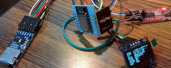
The hardware, like many upcoming Hackaday Prize entries, we’re sure, is based on the ESP8266 WiFi module, with a light sensor, SD card reader, and OLED display. It’s meant to mount directly to a power meter, recording power consumption and pushing that data up the network. It’s simple, but it also allows for very granular monitoring of [Solenoid]’s power consumption, something the electric company’s smart meters can’t compete with.