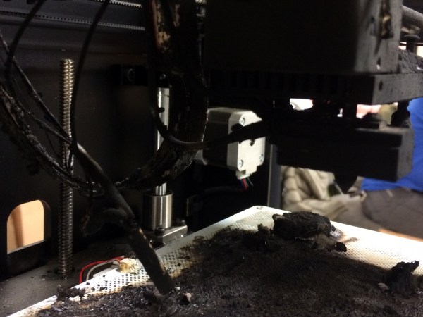
[Jay] out of the River City Labs Hackerspace in Peoria, IL cleared out a jam in his printer. It’s an operation most of us who own a 3D printer have performed. He reassembled the nozzle, and in a moment forgot to tighten down the grub nut that holds the heater cartridge in place. He started a print, saw the first layer go down right, and left the house at 8:30 for work. When he came back from work at 10:30 he didn’t see the print he expected, but was instead greeted by acrid smoke and a burnt out printer.
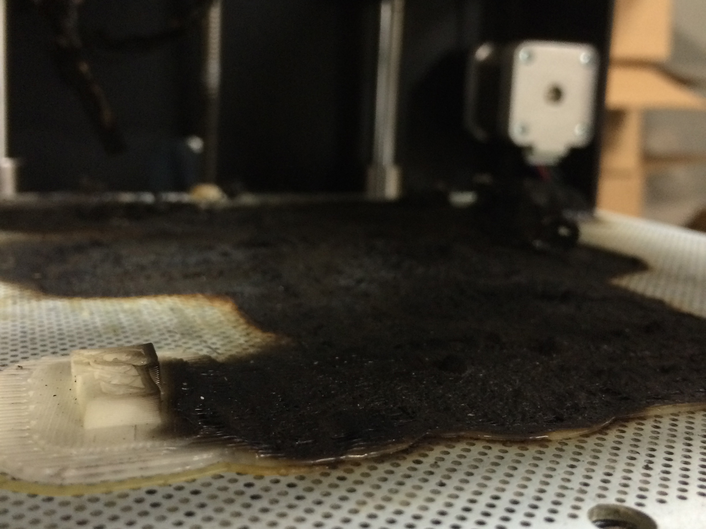
As far as he can figure, some time at around the thirty minute mark the heater cartridge vibrated out of the block. The printer saw a drop in temperature and increased the power to the cartridge. Since the cartridge was now hanging in air and the thermistor that reads the temperature was still attached to the block, the printer kept sending power. Eventually the cartridge, without a place to dump the energy being fed to it, burst into flame. This resulted in the carnage pictured. Luckily the Zortrax is a solidly built full metal printer, so there wasn’t much fuel for the fire, but the damage is total and the fire could easily have spread.
Which brings us to the topics of discussion.
How much can we trust our own work? We all have our home-builds and once you’ve put a lot of work into a printer you want to see it print a lot of things. I regularly leave the house with a print running and have a few other home projects going 24/7. Am I being arrogant? Should I treat my home work with a lesser degree of trust than something built by a larger organization? Or is the chance about the same? Continue reading “Ask Hackaday MRRF Edition: 3D Printers Can Catch Fire”