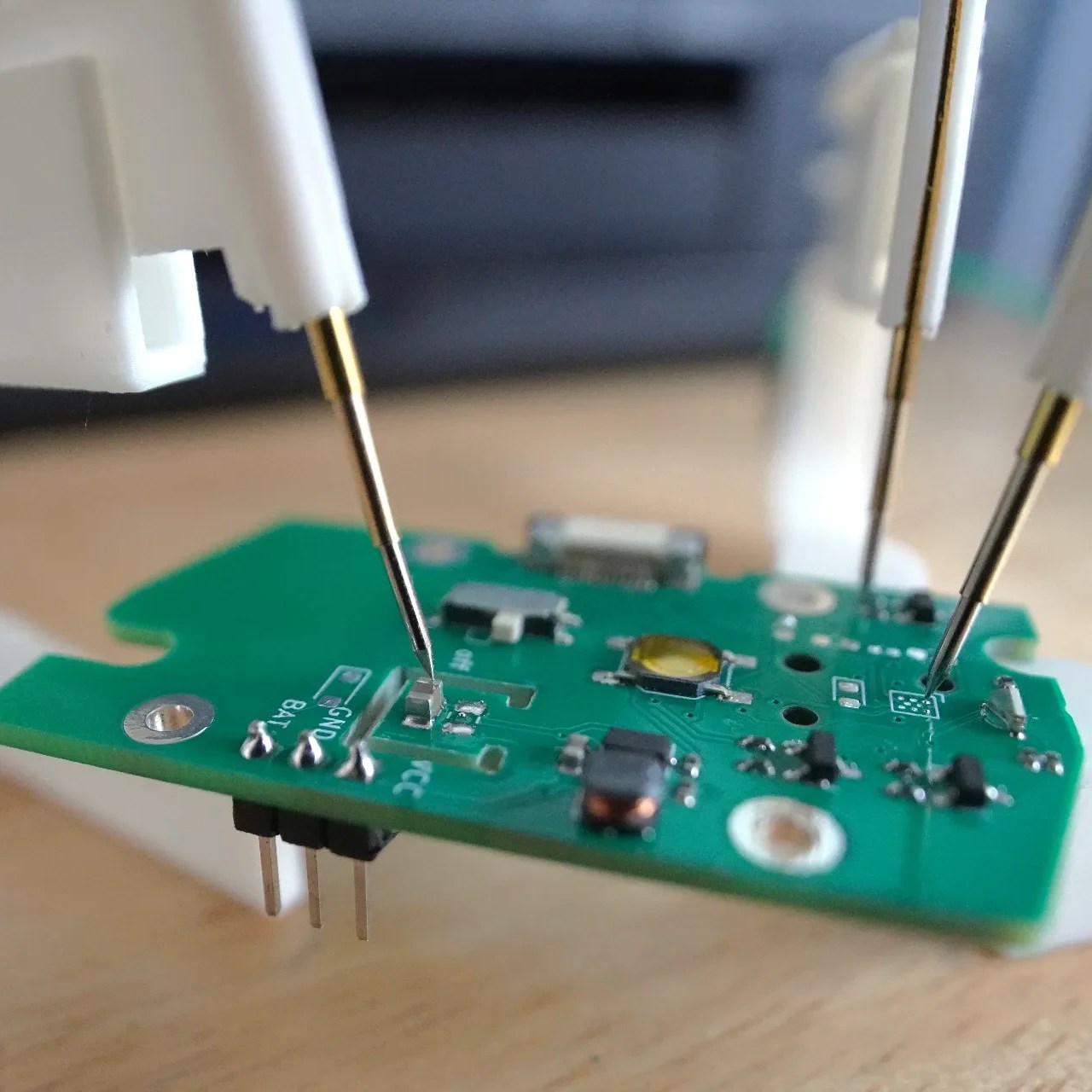
Those of us familiar with PCB work would agree that anything that helps hold probes secure and hands-free to components, traces, or test points is worth looking at. That’s where [2048bits]’ snap probe design comes in. With a little additional and inexpensive hardware, one can have all the hands-free probe clamps one’s workbench can fit!
That first link is where you’ll find a list of required hardware and the CAD files (in .step format) for the probe itself. The obvious approach to making the pieces would be to 3D print them, but we notice the design — while attractive — looks like a challenging print due to the features. We’re not the only ones to see that, and happily there’s already a remix by [user_2299476772] aimed at keeping the essential features while making them easier to print.
If you’re taking a DIY approach to PCB probes, we’d like to remind you that one of our readers discovered dental burrs make absolutely fantastic, non-slip probe tips. This seems like a good opportunity to combine two ideas, and having the CAD files for the probe clamp means modification is straightforward. Let us know on the tips line if you get something working!
We’re used to those high voltage projects which use a self-oscillating transformer circuit with a TV flyback winding, and we have even at times railed against them for their inefficiency compared to a real flyback circuit using the same parts. But what happens if the same idea is used to create a low voltage instead of a high one? [D. Creative] has a soldering gun project doing just this, making a low voltage at a very high current.
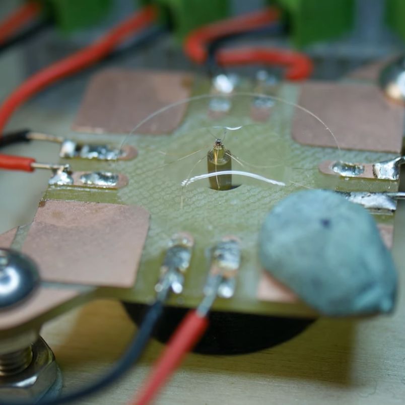
The video of the project is below the break, and while electrically it’s nothing unexpected, we’re taken by the quality of the build. All the parts come from scrap electronics, the main transformer is three ferrite cores with a piece of copper busbar as the secondary. The circuitry is built dead bug style, and it’s housed in a gun-style case made by hand from sheet Perspex. It takes 12 volt power from a laptop power supply, and feeds it to the oscillator which is perched up at the back of the device. The transformer fits in the “barrel”, and a pair of large capacitors fit in the handle. We expect it to get hot, but the duty cycle on these devices in use is probably low enough to keep it from melting.
We like anything that uses scrap parts to make something useful, and we’re particularly taken with the casing of this one. It looks as though the parts come from old switch mode power supplies, something we’ve been known to rob ourselves.
In the world of large language models (LLMs) there tend to be relatively few upsets ever since OpenAI barged onto the scene with its transformer-based GPT models a few years ago, yet now it seems that Chinese company DeepSeek has upended the status quo. Its new DeepSeek-V3 model is not only open source, it also claims to have been trained for only a fraction of the effort required by competing models, while performing significantly better.
The full training of DeepSeek-V3’s 671B parameters is claimed to have only taken 2.788 M hours on NVidia H800 (Hopper-based) GPUs, which is almost a factor of ten less than others. Naturally this has the LLM industry somewhat up in a mild panic, but for those who are not investors in LLM companies or NVidia can partake in this new OSS model that has been released under the MIT license, along with the DeepSeek-R1 reasoning model.
Both of these models can be run locally, using both AMD and NVidia GPUs, as well as using the online APIs. If these models do indeed perform as efficiently as claimed, they stand to massively reduce the hardware and power required to not only train but also query LLMs.
Over the last decade we have brought you frequent reports not from the coolest of hackerspaces or the most bleeding edge of engineering in California or China, but from the rolling prairies of the American Midwest. Those endless fields of cropland waving in the breeze have been the theatre for an unlikely battle over right to repair, the result of which should affect us all. The case of FEDERAL TRADE COMMISSION, STATE OF ILLINOIS, and STATE OF MINNESOTA, v. DEERE & COMPANY relates to the machinery manufacturer’s use of DRM to restrict the repair of its products, and holds the promise to end the practice once and for all.
This is being written in Europe, where were an average person asked to name a brand that says “America”, they might reach for the familiar; perhaps Disney, McDonalds, or Coca-Cola. These are the flag-bearers of American culture for outsiders, but it’s fair to say that none of them can claim to have built the country. The green and yellow Deere tractors on the other hand represent the current face of a company with nearly two hundred years of farming history, which by virtue of producing some of the first mass-produced plows, had perhaps the greatest individual role in shaping modern American agriculture and thus indirectly the country itself. To say that Deere is woven into the culture of rural America is something of an understatement, agricultural brands like Deere have an enviable customer base, the most loyal of any industry.
Thus while those green and yellow tractors are far from the only case of DRM protected repairability, they have become the symbolic poster child for the issue as a whole. It’s important to understand then how far-reaching it is beyond the concerns of us technology and open-source enthusiasts, and into something much more fundamental. Continue reading “The FTC Take Action, Is Time Finally Up For John Deere On Right To Repair?”→
Most of us first spot them as children—the white lines in the blue sky that are the telltale sign of a flight overhead. Contrails are an instant visual reminder of air travel, and a source of much controversy in recent decades. Put aside the overblown conspiracies, though, and there are some genuine scientific concerns to explore.
See, those white streaks planes leave in the sky aren’t just eye-catching. It seems they may also be having a notable impact on our climate. Recent research shows their warming effect is comparable to the impact of aviation’s CO2 emissions. The question is then simple—how do we stop these icy lines from heating our precious Earth?
The first attempt at replicating William McLellan’s miniature motor. (Credit: Chronova Engineering, YouTube)
How small can an electric motor be without resorting to manufacturing methods like lithography? In a recent video, [Chronova Engineering] on YouTube tries to replicate the 1960 McLellan motor that fulfilled [Richard Feynman]’s challenge requirements. This challenge was part of [Feynman]’s 1959 lecture titled There’s Plenty of Room at the Bottom, on the possibilities of miniaturization. A $1,000 reward was offered for anyone who could build an electric motor that was no larger than 1/64th inch cubed (~0.0625 mm3), with the expectation that new manufacturing methods would be required to manufacture a motor this small.
As reported in the December 1960 issue of The Month at Caltech, [William McLellan] walked into [Feynman]’s lab with this tiny marvel that took him 2.5 months of lunch hour breaks to build. Weighing in at 250 micrograms and consisting out of 13 parts, it was constructed using a microscope, a watchmaker’s lathe and a toothpick. Surely replicating this feat would be easy today, right?
The main challenge is that everything is incredibly small. The rotor shaft is 90 micrometers in diameter, and the four coils require winding incredibly thin wire at scales where typical manufacturing methods do not apply. Suffice it to say that it takes massive amounts of patience, creativity and the best (stereo) microscope you can get, yet even with modern optics and materials this first attempt mostly failed.
At the end we’re left with SEM shots of this replication attempt and an immense amount of respect for the skills of [William McLellan] who made a working version in 1960 using much more basic tools during his lunch breaks.
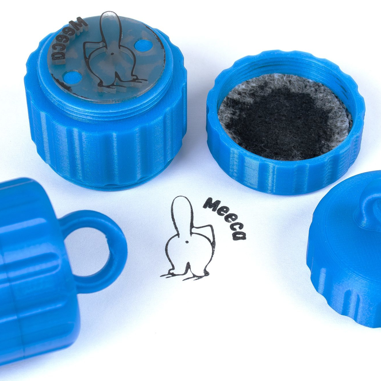
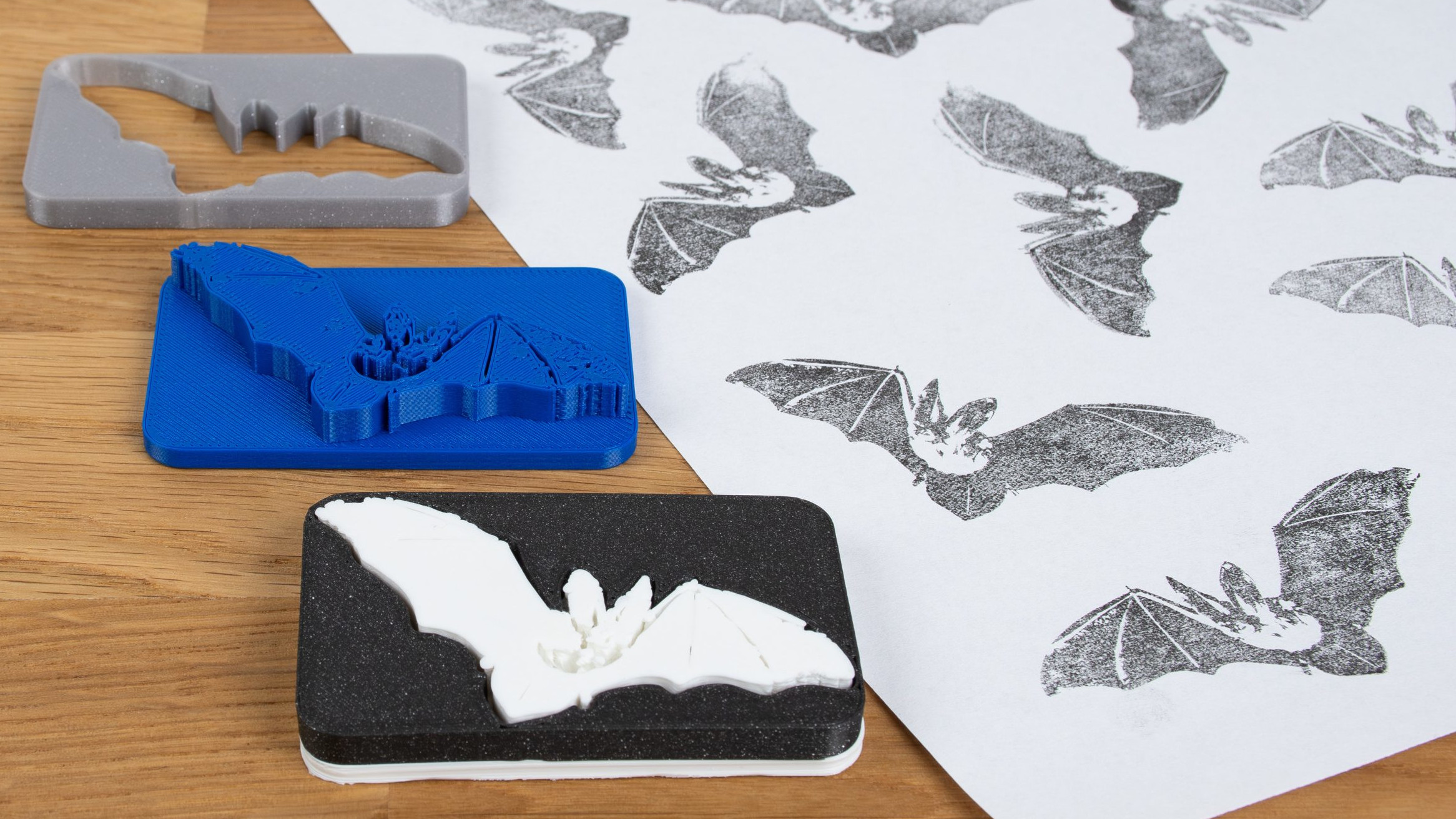
Ink stamps can be fun to make and use, and 3D printers are uniquely positioned to create quality stamps of all kinds with just a little care. As with most things, the devil is in the details and the best results will require some extra work. Luckily, [Prusa] has a blog post that goes through how to 3D print the best stamps and includes concrete recommendations and tips to get the most out of the process.
Resin printers can create stamps too, just ensure a flexible material is used.
What makes a good 3D-printed stamp? It should be easy to use, transfer an image cleanly, and retain ink reasonably well. To hit these bases, printing the stamp face out of a flexible material is probably the most important, but a flat and smooth stamp surface is equally crucial. Satin-finish build plates will give a weathered look to the stamp, but textured build plates in general are no good.
As for the design, turning an image into a 3D object can be a bit challenging for novices, but there are tools that make that much easier now than it used to be. Some slicers allow importing .svg files (scalable vector graphics) with which to emboss or deboss objects, and online tools as well as free software like Inkscape will let folks covert images into .svg format.
Flexible filaments tend to be stringy so they should be dried before use, especially if the stamp design has a lot of separate elements that invite stringing. Any flex filament should do the job, but of course some specific filament brands perform better than others. Check out the full blog post for specific recommendations.
Pausing a print and inserting a pre-printed support piece (removed after the print completes) helps form big overhangs.
The remaining tricky element is that flexible filaments also tend to be poor at bridging, and if one is printing a stamp face-down on the build plate (to get that important, ultra-flat face) then the upper inside of the stamp may need some support for it to come out right. As [Prusa] suggests, this is a good place to use a manual, drop-in pre-printed support piece. Or if one has the ability to print in multiple materials, perhaps print the support structure in PLA since it is just about the only material that won’t completely weld itself to flex filaments. Of course, if one is designing the stamp entirely in CAD, then the best option would be to chamfer the stamp elements so supports aren’t necessary in the first place. Finally, don’t overlook the value of a physical design that makes handling easy and attractive.

 That first link is where you’ll find a list of required hardware and the CAD files (in