Think about the simple tools you use every day. From writing implements to wire spoolers, there is arguably nothing that deserves to be hot rodded more than the things you depend on and might even take for granted.
For mad machinist [Chris], one of those everyday tools is his cutting fluid pot. Of course he already had one. A heavy one. A manly one. But it wasn’t completely ideal, and it wasn’t plated with gold that he prospected, refined, and processed himself. More on that in a minute.
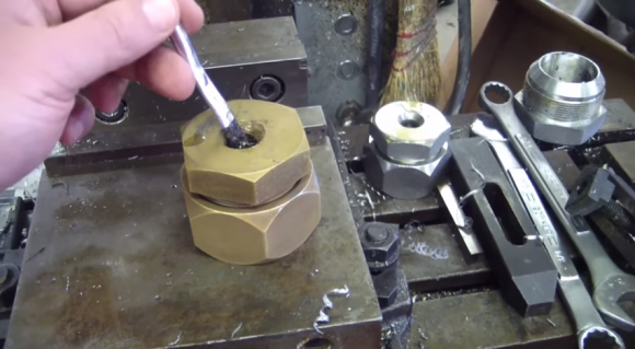
[Chris] had obtained some neodymium ring magnets a while back. He was playing around with them in his shop when he noticed that his cutting fluid applicator brush fit nicely through the center and, being metal, was contained nicely through the wonders of magnetism. It was then that he decided to build a cutting fluid pot that would keep his brush in place and remain upright. Better living through magnetism.
He drilled and chamfered the brush hole out of a #20 JIC hydraulic cap and used the matching plug for the base. In case your catalog is out of reach, those are a 1¼” pair. [Chris] bored tiny pockets in the base for tiny magnets. After bathing both parts in delicious brake cleaner, he adhered all the magnets with LOCTITE®.
Okay, so, he’s done, right? No. Of course not. It did not surprise us to learn that [Chris] is also a miner, and not the 8-bit kind that hates creepers. Over the last two years, he prospected, refined, and other gold-related verbs using equipment he made himself. Just make the jump and watch the video before we give it all away. You’ll laugh, you’ll cry, you’ll be compelled to watch his other videos.
 Come one, come all, to an epic Reddit AMA.
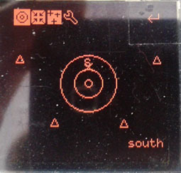 With the advent of electronics in everything, amateur astronomy has never been easier. Telescope mounts that point in the direction of any astronomical object automatically have been around for decades, and the Telrad – a device that paints 0.5, 2, and 4 degree diameter circles in your finder scope’s field of view are available if you’re just too cool for letting a robot do your job.


