Now here’s a really cool engineering degree project — a team of students from a university in Vienna have made a pneumatically driven motor — and fitted it into a quad! (Translated)
The team consists of [Simon Friesacher], [Simon Schedl], [Christoph Sieber] and [Manuel Streith] who all happen to be in the same class as [Maximilian] and [Sebastian] the duo who brought us the VoLumen display, and [Max’s] Ripper CNC!
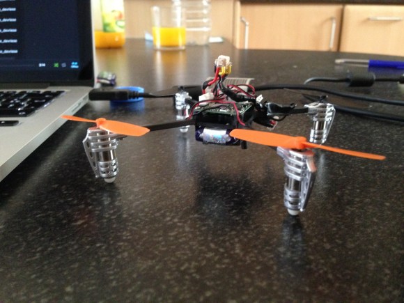
For their main project, the goal was to create an alternative and innovative motor — one that runs off of compressed air, using firefighter’s air tanks. Once they had that figured out, they decided to have some fun with it and put together the Air Quad. It only has a range of a few kilometers, and doesn’t perform quite as well its original gasoline counterpart, but we have to admit, it’s a very slick proof of concept!
Stick around after the break to see a promotional demo of the Air Quad in action!