StarGate Eggbeater

[Jason] used a strip of 142 Adafruit LPD8806 Addressable RGB LEDs to create the StarGate Eggbeater persistence of vision display. The LED strips are controlled by an Arduino Mega, which is used to control the strip and provides 21 bit color control for each LED. The strip is housed into a ring-shaped tube which is mounted onto a rod and bearing to allow it to spin. A 1/4 HP motor is used to spin the ring at 250 RPM creating the POV effect.

One issue when controlling a spinning object is making electrical connections to a spinning object. The LPD8806 requires four connections: power, ground, clock, and data. To make the connections, [Jason] used a MOOG Slip Ring. This allows for the four connections to be made while the ring spins at 250 RPM.

Of course POV demos need videos, so check one out the “boss program” video after the break.

Via Adafruit

Continue reading “StarGate Eggbeater”

UV LEDs Expose PCBs, Gives You A Tan

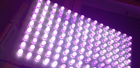
Among the projects that define electronic design, a UV exposure box is right up at the top of the list. These boxes shine UV light on a work piece and are used for everything from exposing photosensitive PCBs to erasing EPROMs. [carlolog] decided to build his own and ended up with a fairly impressive array of ultraviolet LEDs perfect for making PCBs or tanning the back of your hand.

One important thing to remember when making large arrays of LEDs is current consumption and power needed to light the device up. [carlolog] naive assessment of how much power would be required used a 12 volt supply with 135 LEDs and 135 resistors, wasting a lot of energy and producing 24 Watts of heat.

Of course this power consumption can be reduced by putting a few LEDs in series, so [carlolog] wired 3 LEDs together with a 150Ω resistor. This array requires just over 11 Watts and consumes less than 1 Amp; perfect for a desktop UV box.

The enclosure for the box was crafted out of three Ikea photo frames, and a small timer circuit powered by an ATmega8 was added. Now whenever [carlolog] needs to wipe an EPROM, he can put the chip in the box, set the timer, and walk away.

A very nice build, but when dealing with a lot of UV we must remind our readers: do not look into the UV array with your remaining eye.

Adding Digital Readout To A Non-CNC Mill

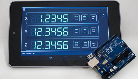
In the quest to add a digital readout to his mill, [Yuriy] has done a lot of homework. He’s sourced a trio of very capable scales, researched what kind of hardware his DRO should be based on, and even built a very cool display using seven-segment LEDs. After nearly a year of work, [Yuriy] finally hit upon something that works well: an Arduino and an Android tablet, perfectly matched for one of the prettiest machine shop displays we’ve ever seen.

[Yuriy] based his build off a trio of digital scales he bought from Grizzly. These scales bolt on to the frame of his mill and send data to their own display. An Arduino was used to pull the data off these scales and sent via Bluetooth to a Nexus 7 Android tablet.

Considering a DRO solely based on an Arduino and a character LCD would look a little chintzy – and the fact Arduinos can’t do floating point arithmetic – we’re really impressed with [Yuriy]’s very elegant solution.

Thanks [Lee] for sending this one in.

Turning A Shipping Container Into A 3D Printer

Built inside a 20-foot shipping container placed on its end, the Kamermaker – ” room maker” in Dutch – is one of the largest 3D printers we’ve ever seen. Able to print objects as big as 2 meter square and 3.5 meters high, the Kamermaker is designed to print huge objects including furniture, architectural elements, and even entire rooms.

The Kamermaker is a collaboration between Architectburo DUS and Utilimaker and the result of wanting to build the world’s largest 3D printer pavilion. Built inside a stainless steel-clad shipping container, the Kamermaker features a scaled-up version of the X, Y, and Z axes you’d find in any other 3D printer. The only change is a scaling up of current designs, allowing it to print small wind turbines covering its surface or, theoretically, a life-size TARDIS.

Because using traditional plastic filament would be prohibitively expensive, the Utilimaker team chose to extrude plastic pellets on the fly as it is used. There’s an excellent video of the filament extruder here along with a walk-through of the machine in operation after the break.

Continue reading “Turning A Shipping Container Into A 3D Printer”

Programming A Microcontroller One Bit At A Time

Imagine you’re stuck on a desert island, hundreds of miles away from the nearest person, and you finally have time to finish that project you’re working on. You have a single microcontroller, but you’re lacking a computer and you need to program an ATtiny13. How do you do it? [androidruberoid] figured out how to manually flash a microcontroller (Russian, surprisingly good translation) using just three switches and a lot of patience.

[androidruberoid]’s ATtiny13 – like nearly all Atmel microcontrollers – are programmed using an SPI interface. This interface requires four signals: SCK, a data clock, MOSI, the data line from master to slave, MISO, data from slave to master, and RESET. By connecting these data lines to buttons, [androidruberoid] is able to manually key in new firmware one byte at a time.

This technique of manually programming bits relies on the fact that there is no minimum speed for an SPI interface. In the video after the break, you can see [androidruberoid] manually programming an ATtiny13 with a simple program. It only lights up an LED, but with enough patience he could key in a simple ‘blink a LED’ program.

Continue reading “Programming A Microcontroller One Bit At A Time”

Kickstarter Isn’t A Store Anymore

Over the past few months, we’ve seen an increasing amount of Kickstarter projects making it into the Hackaday tip line. We don’t mind all these emails from people trying to get their Kickstarter project off the ground, but reading through all the emails of people wanting us to pitch their stuff does get a little bothersome.

It looks like our problem of having to go through dozens of Kickstarter hardware projects a week is about to change. Kickstarter is implementing a few new rules for hardware and product design projects. The new rules prohibit product simulations. This means project creators can’t suggest what the product might do in the future. Only what the prototype can currently do is allowed in the Kickstarter project. Also, product renders aren’t allowed. The only pictures allowed on your Kickstarter project are photos as the prototype currently exists.

There’s also another catch for hardware and product design projects: offering multiple quantities of a reward are prohibited. Of course there’s a provision for things that only make sense as a set (building blocks, for instance), but it looks like funding an Arduino-compatible ATtiny85 board and getting multiple boards is out of the question now.

Of course Kickstarter is looking at the long-term, trying to dissuade project creators from taking the money and running off to South America. We’re wondering what the effect will be in the coming months, though; under these rules Ouya wouldn’t have passed Kickstarter’s litmus test, and smaller projects depending on Kickstarter funding for tooling and molds probably wouldn’t either.

The new changes are probably for the best, and will certainly speed up how long it takes us to go through our email. We’re wondering what HaD readers think of the change, so post your thoughts in the comments after the break.

LED Array Uses Ridiculous Amount Of 14-segment Displays

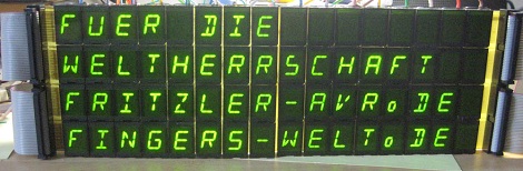
What do you do if you see a bunch of 14-segment LED displays for sale for a penny a piece? [Fritzler], when faced with that conundrum did what any of us would do – he bought 64 14-segment displays and built a huge 16×4 alphanumeric display (German, here’s the translation).

[Fritzler] found a cache of old East German 14-segment displays for €0.01 at electrobi.de (don’t bother, they’re out of stock), and the only thing he could think of was building a gigantic display. He used ULN2803 Darlington drivers for each LED module, but there was still the issue of controlling the entire display.

For that, [Fritzler] decided to make his 16×4 use the same protocol as the Hitachi HD44780 LCD controller. This meant [Fritzler] could wire up his gigantic, power-hungry display to a microcontroller as if it were a simple LCD display.

An amazing amount of work went in to the creation of this display, as evidenced by a pair of pictures showing what [Fritzler] had to solder.

Thanks [freax] for sending this one in.