POE Home Automation Control Panel

poe_home_automation_control_panel

[Scott] wrote in to share a project he is currently working on, a home automation system that relies on Power over Ethernet. While he’s not completely finished, he’s made some great progress, and the work he has done so far definitely piqued our interest.

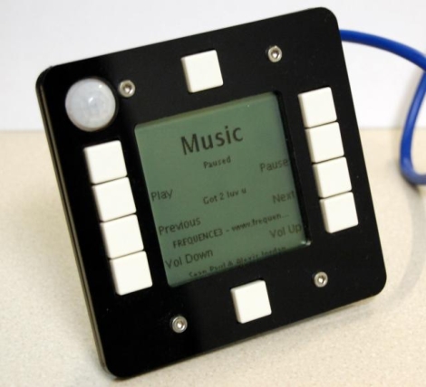
Part of [Scott’s] design relies on some reverse engineered Blackberry screens we showed you a while back. He has constructed a small control panel for his apartment, which incorporates one of the aforementioned Blackberry screens, along with 10 tactile switches and a PIR sensor. The panel is built to be mounted in a wall or as a standalone unit, allowing him to control various lights and appliances throughout his home.

[Scott] spent a lot of time working on the communications protocol and UI for his control panel. As it sits now, the panel takes advantage of a VNC-like protocol he designed, which allows him to interact with a Java application residing on his desktop computer.

Things are looking awesome so far, and [Scott] already has a handful of improvements planned for the near future. We can’t wait to check it out when it’s finished.


N64 Controller Input Using An ATtiny85

[Larsim] worked out the timing necessary to read button and joystick data from an N64 controller using an ATtiny85 microcontroller. The project was spawned when he found this pair of controllers in the dumpster. We often intercept great stuff bound for the landfill, especially on Hippie Christmas when all the student switch apartments at the same time.

Instead of cracking the controllers open and patching directly to the buttons, [Larsim] looked up the pinout of the connector and patched into the serial data wire. In true hacker fashion, he used two 5V linear regulators and a diode in series to step his voltage source down to close to 3.6V, as he didn’t have a variable regulator on hand. It does sound like this causes noise which can result if false readings, but that can be fixed with the next parts order.

The controller waits for a polling signal before echoing back a response in which button data is embedded. This process is extremely quick, and without a crystal on hand, the chip needs to be configured to use its internal PLL to ramp the R/C oscillator up to 16Mhz. With the chip now running fast enough, an external interrupt reads the serial response from the controller, and the code reacts based on that input.

It seems the biggest reason these N64 controllers hit the trash can is because the analog joystick wears out. If you’ve got mad skills you can replace it with a different type.

Electronic Die Rolls Up To 100

If you’re gaming on the road, or just don’t have a die with the right number of sides on hand, an electronic polyhedral die will be quite handy. [Marcus] built this using a printed circuit board of his own design, and we think an electronically simple project like this is a great way to get your feet wet with PCB fab house techniques. He suggests Seeed Studios’ service, or the DorkBotPDX group PCB order. But this would not be a hard project to build on perfboard as well.

The concept is simple. A two-digit 7-segment display shows the value of the top face of your die. when it’s time to roll, just pick up the box and tip it over. A tilt switch senses this action and rolls the die by displaying the next pseudo-random number. The single button, seen here with a pyramid die glued to it, lets you select between die with different number of sides; from 2 (like a coin flip) all the way up to 100.

We like [Marcus’] projects. He’s the same guy that built a scoring system in a game storage box.

Building Your Own Replacement Refrigerator Thermostat

refrigerator_thermostat_repair

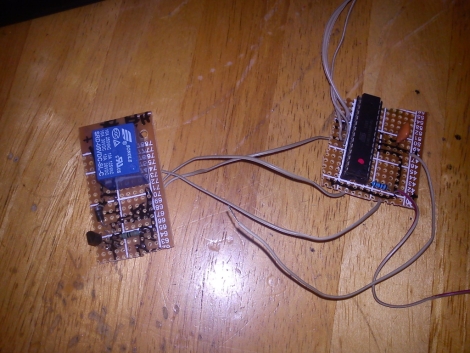
[Ron’s] refrigerator broke shortly after he came home from his weekly grocery trip, and since this was his second dead fridge in three years, he wanted to fix it rather than buy a new one…again. It turns out that the thermostat was toast, and a replacement would cost him $80. That was well more than he was willing to pay, but his groceries were starting to get warm, so he had to do something.

Being the tinkerer he is, he figured he could rig up his own thermostat that would work at least as well as the one that died on him. He scavenged an ATmega328 from a failed project, and after digging around online, put together the most barebones Arduino setup he could find. The microcontroller is tucked away in the back of the refrigerator where the old thermostat used to live, and takes input from a TMP36 temperature sensor, triggering a relay to start the refrigerator’s compressor whenever the the temp goes above 4°C.

[Ron] says his fix is just about the “worst kludge ever”, but as he saved $80 in parts and $150 in labor, we’re inclined to think it’s a job well done.

Ultimaker Quality FAQ Is Like Porn For 3D Printers

Do you think it’s not really possible to get amazing resolution from extruder-based 3D printers? You’re wrong, and this post about the attainable quality of prints on the Ultimaker proves it. The Yoda bust seen above was printed with a layer thickness of 0.02mm. This is a hack in itself because this process actually used two different layer thicknesses. The interior of the print, which you can’t see, but serves as a support mechanism for the object was printed at 0.04mm, with just the visible perimeter printed in the smaller thickness. That trickery is just fine with us if this is the result.

[Dave Durrant] discusses the press the Ultimaker has received, which mostly focused on the relatively fast printing process this hardware uses. But he didn’t think the story of the quality you can get with the device was being told. So he put out a call on the mailing list to send in pictures of high-quality 3D prints and he wasn’t disappointed by the response. You’ll see images of busts, bodies, gears, animals, and art pieces. There’s information about how they were printed, but even those not interested in the particulars will appreciate the macro photography that gives you an up-close look at how far we’ve come with these table-top rapid prototyping machines.

[Thanks Taylor]

Solar Charger For Occupy Boston

As soon as the team at Revolt Labs heard Occupy Wall Street was coming to Boston, they decided to pick up their soldering irons in support of the throngs of protestors. They came up with a Solar charging USB box to keep those cell phones and digital cameras charged.

The case came direct from an Army surplus store. Originally, the box was used by the Dutch military to test the air for poison gas and signal when it was safe to remove a gas mask – hopefully not a portent of things to come.

On top of the box is five solar panels that output two watts each. A bit of breadboard holds a 7805 voltage regulator, a few caps and a diode. This regulated output goes to a USB hub and provides power for recharging.

For a cheap and easy project for our brothers without arms, we couldn’t think of a better project for the Occupy Boston tent city. Of course heating units will be needed at the Occupy protests this winter, but at least now the protesters have the means to power their communications equipment.


update: Once again, this has devolved into political argument and name calling. We, as hackaday, really couldn’t care less which party you are for or what your political beliefs are. We want to talk about the project, in this case a portable solar charger. We go to other sites to argue politics. Maybe you should try here.

Build A Binary Wall Clock For Just A Few Bucks

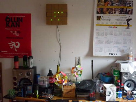
The weekend is almost here and if you’re looking for an afternoon project consider building your own binary wall clock. [Emihackr97] built the one you see above using parts on hand, but even if you put in an order for everything, it won’t cost you much.

He used a cardboard box as the housing for the clock, marking a grid for the LEDs on the face and drilling holes to house them. Two columns for hours and another two for minutes let the clock display 24-hour time with alternate firmware for 12 hour time. Since there are two buttons – one to set hours, the other to set minutes – a little coding would make it possible to select between the two either by clicking both buttons at once, or holding down one button.

[Emihackr97] is driving the display with an ATmega48, which is a pin-compatible replacement for the ATmega168/328. Those chips are the type most commonly found on Arduino boards an indeed this project is running the Arduino bootloader, but uses an ISP programmer and breadboarded circuit to keep the costs low. There are plenty of pins to drive the 13 LEDs directly, making the soldering quick and painless. Check out a demo clip after the break.

If you’re successful at this build and get the itch for something with more style, there’s a ton of ways to spice up the look of a binary clock.

Continue reading “Build A Binary Wall Clock For Just A Few Bucks”