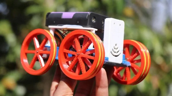
Art of 3D printer in the middle of printing a Hackaday Jolly Wrencher logo

PrusaSlicer Now Imports STEP Files, Here’s Why That’s A Big Deal

PrusaSlicer has a new feature: the ability to import a CAD model for 3D printing. Starting in version 2.5.0-beta1, PrusaSlicer can import STEP format 3D models. An imported STEP file is converted to a triangle mesh on import (making it much like a typical .stl or .3mf file) which means that slicing all happens as one would normally expect. This is pretty exciting news, because one is not normally able to drop a CAD format 3D model directly into a slicer. With this change, one can now drag .stp or .step files directly into PrusaSlicer for printing.

First, a brief recap. In the world of 3D models there are two basic kinds: meshes and CAD models. The two work very differently, especially when it comes to editing. 3D printing has a long history of using .stl files (which are meshes) but making engineering-type changes to such files is difficult. Altering the size of a thread or changing mounting holes in a CAD model is easy. On an STL, it is not. This leads to awkward workarounds when engineering-type changes are needed on STLs. STEP, on the other hand, is a format widely supported by CAD programs, and can now be understood by PrusaSlicer directly. Continue reading “PrusaSlicer Now Imports STEP Files, Here’s Why That’s A Big Deal”

Motorized Camera Mount Was Once A 3D Printer

If you plan on building your own motorized camera mount, a 3D printer can definitely be of help. But in this case, [dslrdiy] didn’t use it for printing out parts — finding himself with little use for an old printer built from scrap back in the day, he decided to repurpose it and turn it into a remote controlled DSLR camera mount that’s capable of panning, tilting, and sliding.

The main goal was to not only salvage the stepper motors and controller board, in this case an Arduino Mega 2560 with RAMPS board, but also to keep the original firmware itself in use. For this to work, [dslrdiy] redesigned the mechanical parts that would allow him to perform the different camera movements using regular G-Code instructions operating the X, Y, and Z axes to pan, tilt, and slide respectively.

The G-Code instructions themselves are sent via UART by an accompanying control box housing an ESP32. This allows the camera mount to operated by either via joystick and buttons, or via serial Bluetooth connection, for example from a phone. The ESP32 system also allows to set predefined positions to move to, along with speed and other motor tweaks. You can see it all demonstrated in the video after the break.

While there’s simpler solutions for camera mounts out there, this is certainly an interesting approach. It also shows just how far desktop 3D printers have come if we already find the older generations repurposed like this. For more of [dslrdiy]’s work with 3D printers and cameras, check out his customizable lens caps.

Continue reading “Motorized Camera Mount Was Once A 3D Printer”

Art of 3D printer in the middle of printing a Hackaday Jolly Wrencher logo

Forget The UV Resist Mask: Expose Custom PCBs Directly On Your SLA Printer

For the enterprising hobbyist and prototyping hardware developer, creating custom PCBs remains somewhat of a struggle. Although there are a number of approaches to go about this, they usually involve printing or drawing a mask that is used to expose the photoresist layer on the to-be-etched PCB. Here [Andrew Dickinson]’s Photonic Etcher project provides an intriguing shortcut, by using the UV source of an MSLA 3D printer directly after converting the project’s Gerber files into a format the MSLA printer can work with.

The concept is as simple as can be: since MSLA printers essentially function by creating a dynamically updated UV mask (either via an LCD panel or DLP system), this means that an MSLA printer can be used to expose the PCB’s UV-sensitive photoresistive coating, effectively making the mask there insoluble during the etching step. This can be done with negative as well as positive photoresistive coatings, depending on the use case.

The obvious advantage of this approach is that you don’t need an additional UV source or any kind of separate mask, only an MSLA printer with a large enough work area to fit the PCB you wish to expose. One limitation of [Andrew]’s project at this point is that it can only convert Gerbers to PWMS (Photon Mono) files, but this can presumably be fairly easily extended to support more MSLA printers.

Want Faster Extrusion But Don’t Have A Volcano? Nuts!

A lot of people want to print faster. Maybe they don’t like to wait, or they need to print a lot of things. Maybe it is just human nature to want to push things to go faster. The problem is, if you move filament too fast it may not have time to melt inside the hot end. To combat that, some people install a “volcano” — a larger heat block that takes a special longer nozzle. The melt zone is longer so there is more time for the filament to liquefy before shooting out of the nozzle. This is also a problem if you are using a very large nozzle size. But what if you don’t have one of these special hot ends? According to [Stefan], you can use a normal hotend with a volcano-style nozzle just by adding some common nuts. You can see the explanation in the video, below.

The idea came from a few commercial offerings that allow converting between different-sized melt zones. Some of these use the same idea. But, if you are familiar with [Stefan’s] videos, you know he tested the results thoroughly. The tests reveal that a standard V6-style hotend can handle rates of just over 9.8mm/second. with a 0.4mm nozzle at 210C and is usable beyond that. A true volcano hotend. starts deviating from the ideal at about 15mm/second and, also, is usable at even higher rates. But what about just using a long nozzle in a regular block with or without the nuts?

Continue reading “Want Faster Extrusion But Don’t Have A Volcano? Nuts!”

Welcome To Ziptie City

Gravity, magnetism, the weak and strong nuclear forces; sure they hold a lot of stuff together. But the other binding force of nature that demands your utmost respect? Zip ties.

Or at least that’s [Alan Reiner]’s take on the combination of cable ties and 3D printing. (Video, embedded below.) So he’s designed a demo model, Zip Tie City, that goes through a number of the possibilities that designing in zip-tie channels offer.

He then designs a multi-output battery box with a ton of zip tie holds that keep wiring in check and hold modules and batteries where they belong.  (And releases some magic smoke, but even zip ties can’t keep that stuff inside.)

We love zip ties for those situations where screws are overkill or a simple solution is sufficient. Designing channels for zip ties is a pure win, and makes use of the unique advantage of 3D printing; these would be horrible to try to subtractively machine into a part.

Zip ties aren’t the only game in town, though. If you need a glue, our own [Tom Nardi] went through his local hardware store and tested out the options in this must-read classic piece.

Thanks for the tip to [Keith Olson], who wants you to check out Zip Tie Guy (video) while you’re in the mood.

Continue reading “Welcome To Ziptie City”

Adding Perlin Noise To 3D Printed Parts, With Python

Want to add a bit of visual flair to 3D printed parts that goes maybe a little more than skin-deep? That’s exactly what [volzo] was after, which led him to create a Python script capable of generating a chunk of Perlin noise, rendered as an STL file. What does that look like? An unpredictably-random landscape of hills and valleys.

The script can give printed parts a more appealing finish.

The idea is to modify a 3D model with the results of the script, leaving one with something a bit more interesting than a boring, flat surface. [volzo] explains how to use OpenSCAD to do exactly that, but it’s also possible to import the STL file the script creates into the CAD program of one’s choice and make the modifications there with some boolean operations.

If the effect looks a bit bit familiar, it’s likely because he used the method to design part of the 3D printed “toy” camera that we featured recently.

[volzo]’s method isn’t entirely plug and play, but it could still be a handy thing to keep in your back pocket when designing your next part. There are also other ways to modify the surfaces of prints for better aesthetics; we’ve previously covered velocity painting (also known as ‘tattooing’ in some slicers) and also fuzzy skin.

Perlin noise was created by [Ken Perlin] in the early 80s while working on the original Tron movie as a way to help generate more realistic-looking textures. It still fulfills that artistic function in a variety of ways, even today.

Upgraded Film Scanner Handles Bigger Formats At No Cost

Film scanners are a useful tool for digitizing slides and negatives, and the Plustek 8100 that [Christian Chapman] had was capable, but limited to small format film only. Rather than pay for a much more expensive medium format scanner that could handle 120 film, he modified his 8100 to accomplish the same thing with a combination of good old software and hardware tampering.

On the software side, [Christian] modified a driver for the Plustek 8100 so that it sweeps the scan head further than usual. At the application level, to scan medium format frames, it does a total of four scans: one for each quadrant. The results get stitched together in software with a thoughtfully-designed shell script that provides previews and handles failures and restarts gracefully.

Hardware-wise, the scanning carriage needs modification to ensure nothing interferes with the scan head as it moves further than originally designed. Some CAD and 3D printing made short work of this. Incidentally, this hardware mod is an excellent demonstration of one of the core strengths of 3D printing: the ability to make geometrically-straightforward objects that would nevertheless be troublesome or impractical to construct in any other way.