High speed photography is fun. Ultra high frame rate video, even more so. But since not many of us have access to $10,000 HFR cameras… we have to make do with long exposure shots a perfectly timed camera flash. You can design a system to trigger the flash at just the right millisecond — but they’re still pretty expensive typically.
[Electronupdate] has a 100W LED module and penchant for Arduino Nanos — so he wondered if he could make an affordable high speed camera rig — and he did.
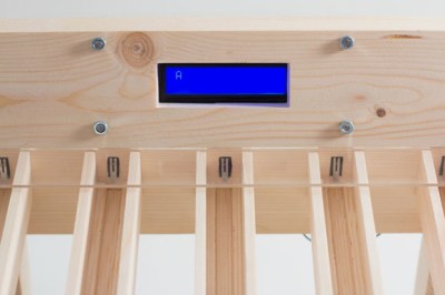
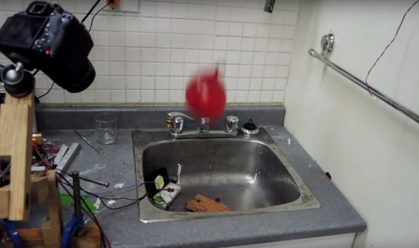
It’s a pretty slick little setup. He has a limit switch mounted to a nail on a piece of wood — when the water balloon drops on it, it triggers the mechanical switch. The Arduino then triggers the LED flash, which is quite a large load and requires a High Side Switch to operate. A small LCD and series of buttons allow him to dial in the time offset just right in order to get some awesome photos of a water balloon exploding.