LED and LCD displays are a technological marvel. They’ve brought the price of televisions and monitors down to unheard-of levels since the days of CRTs, but this upside arguably comes with an aesthetic cost. When everything is covered in bland computer screens, the world tends to look a lot more monotonous. Not so several decades ago when there were many sharply contrasting ways of displaying information. One example of this different time comes to us by way of this split-flap display that [Erich] has been recreating.
Split-flap displays work by printing letters or numbers on a series of flaps that are attached to a spindle with a stepper motor. Each step of the motor turns the display by one character. They can be noisy and do require a large amount of maintenance compared to modern displays, but have some advantages as well. [Erich]’s version is built out of new acrylic and MDF, and uses an Arduino as the control board. A 3D printer and CNC machine keep the tolerances tight enough for the display to work smoothly and also enable him to expand the display as needed since each character display is fairly modular.
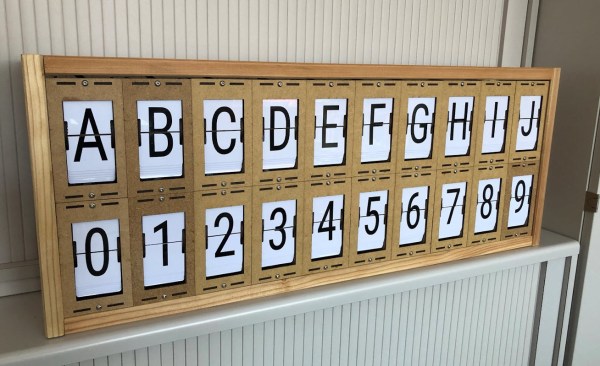
Right now, [Erich]’s display has 20 characters on two different rows and definitely brings us back to the bygone era where displays of this style would have been prominent in airports and train stations. This display uses a lot of the basics from another split flap display that we featured a few years ago but has some improvements. And, if you’d prefer restorations of old displays rather than modern incarnations, we have you covered there as well.