Adding A Battery Gauge To A Project With Zero Parts

The typical way of doing a low battery detector is throwing a comparator in the circuit, setting it to measure a certain threshold voltage, and sending that signal off to a microcontroller or other circuit to notify someone the battery is going dead. [Josh] has a simpler way using an 8-bit AVR and zero other parts.

The chip [Josh] is using is the ATtiny84. The ADC in this chip is usually used to measure an unknown voltage against a reference voltage. The trick [Josh] is using is to do this in reverse: The internal 1.1 Volt reference voltage is measured against an unknown scale, namely the input voltage.

The value provided by the ADC on the chip will always be Vin times 1024 over the reference voltage. Since Vin will be 1.1 V in this case, the ADC value is known, it’s only a matter of doing some 6th grade algebra to determine the value of the input voltage.

[Josh] put together a small demonstration where the chip blinks out the number of volts its receiving from a bench power supply. By blinking a LED, it can blink out the current value of VCC as integers, but by using this technique you should be able to get a fairly fine-grained reading of what VCC actually is. Video below.

Continue reading “Adding A Battery Gauge To A Project With Zero Parts”

Redesigned Bike Light Controller

[JP] was looking for a bicycle light to do some night biking around his home. He found a reasonably priced light that suited his needs, but when he started using it he found that the controller was a little lackluster. To solve some of its problems, he ended up building his own lighting controller from scratch.

The original controller’s main problem was that the it didn’t debounce the input from the single pushbutton. This meant that a single press of the button might cause it to cycle through two or three different modes, which was inconvenient and annoying. The new controller took care of this along with implementing several new brightness modes and a “strobe” mode for commuting to work to help alert other drivers of [JP]’s presence on his bicycle.

While [JP] notes that an Arduino would have been very easy to use in this situation, it wouldn’t have fit in the original enclosure. He went with an 8-pin ATtiny45, which was perfectly sized for what he needed. Everything fit together perfectly and is much more useful than the original. Maybe next he could pair it with a light that is even brighter than the one he’s currently using.

AVR Programmer

Inexpensive AVR Programmer Made From Five Components

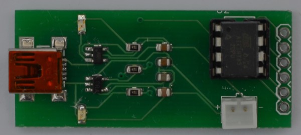
If you want to program an AVR chip as inexpensively as possible, then [Ian’s] solution might just be for you. He built an AVR programmer using only four components. This design is based on the vusbtiny AVR programmer design, with a few components left out.

[Ian’s] design leaves out two of the resistors and two diodes, leaving just four components. These include a 1.5k resistor, a small capacitor, a USB connector, a six pin header, and an ATtiny45. He admits that this may not be exactly up to USB spec, but it does work.

This is one of those projects that is really an exercise in “will it work?” more than anything else. The fact that you need to first program an AVR chip means that this wouldn’t be useful in a pinch, because you would already have to have a working programmer. Nonetheless, it’s always fun to see what can be done with as little as possible.

Now Let’s See The World’s Largest Arduino

A few days ago we saw what would have been a killer Kickstarter a few years ago. It was the smallest conceivable ATtiny85 microcontroller board, with resistors, diodes, a USB connector, and eight pins for plugging into a breadboard. It’s a shame this design wasn’t around for the great Arduino Minification of Kickstarter in late 2011; it would have easily netted a few hundred thousand dollars, a TED talk, and a TechCrunch biopic.

[AtomSoftTech] has thrown his gauntlet down and created an even smaller ‘tiny85 board. it measures 0.4in by 0.3in, including the passives, reset switch, and USB connector. To put that in perspective, the PDIP package of the ‘tiny85 measures 0.4 x 0.4. How is [Atom] getting away with this? Cheating, splitting the circuit onto two stacked boards, or knowing the right components, depending on how you look at it.

USB [Atom] is using a few interesting components in this build. The USB connector is a surface mount vertical part, making the USB cord stick out the top of this uC board. The reset button is extremely small as well, sticking out of the interior layer of the PCB sandwich.

[AtomSoft] has the project up on OSH Park ($1.55 for three. How cool is that?), and we assume he’ll be selling the official World’s Smallest Arduino-compatible board at Tindie in time.

What Is This, A Microcontroller Board For Ants?

You youngins probably don’t remember this, but a few years ago there was an arms race on Kickstarter to create the smallest Arduino-compatible microcontroller board. Since then, a few people have realized they can make more money on Kickstarter through fraud or potato salad, and the race to create the smallest ‘duino board petered out.

It’s a shame [Meizhu] wasn’t part of the great miniature Arduinofication of Kickstarter, because this project would have won. It’s an Atmel ATtiny85, with USB port, resistors, diodes, reset button, LED, and pin headers, that is just 72 mils larger than the PDIP package of the ‘tiny85. Outside of getting a bare die of ‘tiny85s, there isn’t much of a chance of this board becoming any smaller.

[Meizhu] was inspired to create this board from [Tim]’s Nanite 85, which up until a few days ago was the current champion of micro microcontroller boards. With a bit of work in KiCAD, the new board layout was created that is just a hair larger than the 0.4″ x 0.4″ footprint of the PDIP ATtiny85. There were a few challenges in getting a working board this small; you’d be surprised how large the plastic bits around pin headers are, but with some very crafty soldering, [Meizhu] was able to get it to work.

Infrared-controlled Light Switch

If you’re looking for your first electronics project, or a project to get someone else started in electronics, [Vadim] has you covered. Back when he was first starting out in electronics he built this infrared-controlled light switch that works with a standard TV remote control.

[Vadim]’s first few projects ended up as parts for other projects after they were built, so he wanted to build something useful that wouldn’t ultimately end up back in the parts drawer. The other requirements for the project were to use a microcontroller and to keep it simple. [Vadim] chose an ATtiny2313 to handle the RC-5 IR protocol and switch the light.

The circuit still has a switch to manually control the lights, preserving the original functionality of the light switch. The rest of the design includes a header for programming the board and another header for tying into the high voltage lines. This is a great project for anyone who knows what they’re doing with mains power but is just getting started with microcontrollers. If properly designed and implemented you’ll never stumble across a room to turn the lights out again!

Perhaps mixing high and low voltages on the same circuit board doesn’t spark your fancy or you can’t modify the light switch in your place of residence? Check out this mechanically-switched light switch.


Simple Touch Controller Frees Up USB Port

touch screen demonstration using text

[typ.o] was working on a Raspberry Pi project and found himself running short on USB ports. The project required a touch screen interface, which takes up one of the ports. Since he was only using the screen in text mode, he decided to ditch the original USB controller and make his own.

The ever popular Attiny85 is deployed to handle the task, and is interfaced between the resistive touch panel and the Raspberry pi, using only three pins from the GPIO port. The Attiny85 runs off the 3 volt supply from the raspi, so no level shifter is needed, helping to keep his board super simple.

The calibration and calculation of the touched character location is done by a Python script running on the raspi. [typ.o] is a fan of the KISS principle, and it shows. Be sure to check out his site for all source code, schematics and a video demonstrating this simple but effective solution.