You can find galvanized steel pipes at Home Depots and construction sites all around the world. These relatively thin-walled steel pipes would make for great structural members if it weren’t for the fact they were covered in a protective layer of zinc. This layer of galvanization lends itself to crappy welds and some terrible fumes, but badass, TV personality, and hacker extraordinaire [Hackett] shows us how to strip the galvanization off these pipes with chemicals available at any hardware store.
Since the galvanization on these pipes covers the inside and the outside, grinding the small layer of zinc off these pipes is difficult at best. To be sure he gets all the zinc off this pipe, [Hackett] decided to chemically strip the pipes with a cup full of muriatic acid.
The process is simple enough – fill a cup with acid, dunk the ends of the pipes, and clean everything up with baking soda. A great way to turn scrap pipe into a usable material, make a cool paper mache volcano, and avoid ‘ol galvie flu
Here’s [Phil] showing off the components he used to make an HHO generator. The device uses household items to generate hydrogen and oxygen from water using electrolysis.
He’s using a plastic Nesquik container as the vessel for his experiment. Inside is water doped with a bit of baking soda. The lid plays host to the majority of components. There are electrodes which stick through the lid of the container. To help boost the productivity of the generator these electrodes have several metal washers suspended between. It’s importnat to avoid a short circuit so they’re mounted with the plastic bolt from a toilet seat, and isolated using hot glue. A plastic tube used collects the gasses. You can tweak the ratio of what’s being collected by reversing the polarity of the battery.
It’s interesting to see soap bubbles lit on fire in the demo video. But there are more serious uses for this concept. People have been working on making it feasible to power cars from the hydrogen generated this way. We’ve also seen a plastic bottle rocket powered from an HHO generator, and there’s always the thought of building your own miniature dirigible.
This experiment was started at Trinity College Dublin way back in 1944. Its purpose is to prove that tar flows, and indeed it does let go of a drop about every ten years. The thing is that nobody has ever seen that happen, bringing up the “if a tree falls in the forest” scenario. The Nature article on this event even mentions another experiment whose last drop was missed because the camera monitoring it was offline. This time around they did get some footage of the (un)momentous event which you can see below.
So here’s the challenge for clever hackers: What’s the easiest rig you can think of that won’t just continuously film the experiment but can also ensure that you get the goods on tape when a drop does fall? We see all kinds of high-speed shutter triggers — here’s one of the latest. But we don’t remember seeing an extremely slow version of the same. Let us know your idea by leaving a comment.
If you are using live plants in your aquarium you must remember to fertilize them at regular intervals. Being a bit forgetful, [Deven] automated the process by building this auto-doser.
There are three different chemicals which are dispensed by the system. They are stored in the drink bottles seen above. Each has a plastic tube which runs up to the dosing motors mounted on the black box. [Deven] sourced the motors from eBay. They are designed for this type of application.
Inside the black box is the Arduino that handles timing and switches the motors. The control circuitry is protected using one MOSFET for each. To keep the fish safe the outflow is directed right into the aquarium pump so that the concentrated chemicals are quickly dispersed through the entire tank.
When you think of a radiation detector, you’re probably thinking of a Geiger tube and its high voltage circuitry. That isn’t the only way to measure gamma radiation, though, and [Alan] has a great circuit to measure even relatively weak radiation sources. It uses a very small photodiode, and draws so little power it’s perfect for projects with the smallest power budgets.
The detector circuit uses a miniature solar cell and a JFET wired up in a small brass tube to block most of the light and to offer some EM shielding. This, in turn, is attached to a small amplifier circuit with a LED, Piezo clicker, and in [Alan]’s case a small counter module. The photodiode is actually sensitive enough to detect the small amounts of gamma radiation produced from a smoke alarm americium source, and also registers [Alan]’s other more powerful radioactive sources.
The circuit only draws about 1mA, but [Alan] says he can probably get that down to a few micoAmps. A perfect radiation sensor for lightweight and low power applications, and gives us the inspiration to put a high altitude balloon project together.
This is exactly what it looks like. [Oleg] calls it soldering in inert atmosphere, but it’s just a toaster oven reflow hack dropped into a container full of carbon dioxide.
Why go to this trouble? It’s all about solder wetting. This is the ability of the molten solder paste to flow into all of the tinned areas of a board. [Oleg] talks about the shelf life of hot air leveled PCB tinning, which is about six months. After this the tin has oxidized. It will certainly not be as bad as bare copper would have, but it can lead to bad solder joints if your PCBs are more than about six months off the production line. This is one of the reasons to use solder flux. The acid eats away at the oxidized layer, exposing tin that will have better wetting.
But there is another way. Soldering in the absence of oxygen will also help the wetting process. CO2 is heavier than air, so placing the reflow oven in a plastic container will allow you to purge air from the space. CO2 canisters are cheap and easy to acquire. If you keg your own homebrew beer you already own one!
Years ago we covered using thermite to destroy a hard drive. The idea is that if you melt through the platters, the data is completely unrecoverable. There are tons of videos of people doing this, but they all have a similar format. There’s a hard drive, with a flower pot or soda can sitting on top full of thermite. They then light this with a strip of magnesium and a torch.
I wanted to do something a little different. I wanted to implement thermite as a self destruct mechanism inside the device. To do this, I had to come up with a way to ignite the thermite. This stuff is very difficult to light. You have to get it really really hot. The easiest way is to use magnesium, which itself isn’t the easiest thing to light.
What I finally landed on was an ignition system that uses model rocket igniters, gun powder, and magnesium to light the thermite. The model rocket igniter can be set off from the 12v line inside your computer. However, it isn’t hot enough to light magnesium shavings, much less thermite. To get it to work, I needed to add some gunpowder. A small amount of gun powder would get hot enough to light the magnesium shavings, which in turn were hot enough to light the thermite. I had to be careful though, because too much gunpowder would cause a rapid expansion, blowing the thermite everywhere instead of lighting it. You can actually see some red thermite being blown out of the external hard drive and the laptop as the gunpowder ignites.
gun powder
model rocket igniters
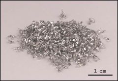
magnesium shavings
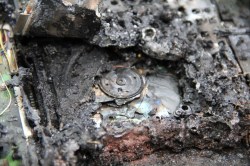
Effectiveness of external hard drive self destruction:
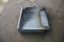
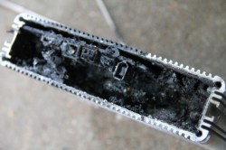
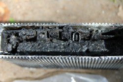
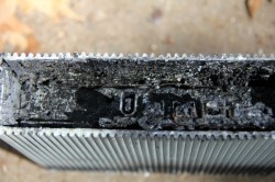
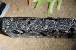
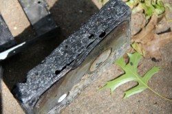
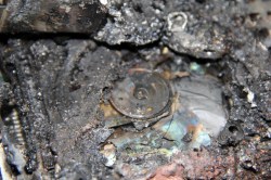
I wasn’t sure about this one. There isn’t a whole lot of space for thermite and the ignition system inside the box. On top of that, the only space was at the side of the hard drive, where the walls are the thickest. I had no idea if the small amount of thermite I used would penetrate the drive. It did, just barely as you can see in these pictures. It looks as if it pooled in the screw holes and made it inside. The platters are damaged.
burnt unit
looking down on hard drive
you can see a hole in the drive from this angle
yuck
yep, appears to be the screw hole
platters are damaged, but not as effective as thermite to the top
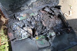
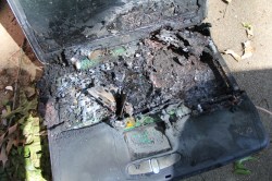
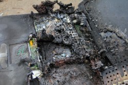
Effectiveness of laptop destruction:
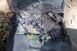
I decided to completely replace the cd rom with thermite. This gave me a ton of space to put things. I was pretty positive this would work. The hard drive is in the center of this laptop, which meant I had to place it on its side for this to be effective. You can see the thermite work its way down toward the drive in the video. As you can see in the pictures below, the drive cover is completely gone and the platters are destroyed. Success!
crusty
hard drive is center of the image
platters are clearly visible
completely fried
un covered
no data coming off that
Since this system can be powered by batteries or the internal power of your computer, it can be put inside a working device only to be used when needed. Obviously it is a ridiculous fire hazard that no one should bother with. It was a fun experiment though and I really feel like it is something that would fit in well in the world of [James Bond]