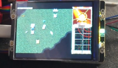
An IBM PC showing "68000 IBM PC" on its monitor

IBM PC Runs BASIC With Motorola 68000 CPU Upgrade

Although ARM CPUs have been making headway in several areas of computing over the last decade or so, the vast majority of desktop, laptop and server CPUs are still based on the x86 architecture. How that came to be is no secret, of course: IBM chose the Intel 8088 to power its model 5150 PC back in the early 1980s, and since it became the dominant PC platform, everyone else followed suit. But what if IBM’s purchasing department had got a good deal at Motorola instead? [Ted Fried] has been experimenting with that scenario, by equipping an IBM PC with a 68000 CPU.

To be fair, he didn’t use an actual Motorola chip; instead, he emulated a 68k core on a Teensy 4.1 and implemented the 8088’s bus interface on its pins. The emulated core does exactly the same thing an actual CPU would do, while the rest of the computer works the same way it always did – data is stored in the motherboard’s DRAM chips, keystrokes are processed by the standard 8255 chip and progam output is displayed on the monitor through the MDA video card. Continue reading “IBM PC Runs BASIC With Motorola 68000 CPU Upgrade”

Squeeze Over A Minute Of Movie Filming Onto A 35mm Still Cartridge

There’s an allure to shooting film in the digital age which isn’t quite satisfied by digital filters for your smartphone camera. Aside from the technical challenge of working with a medium limited in sensitivity compared to its electronic replacement there are aesthetic reasons for wanting to shoot with particular lenses not found on any modern cameras. Sadly though, movie film in formats such as Super 8 is expensive to buy and even more expensive to develop.

It’s a problem [Blaž Semprimožnik] addressed with his Okto 35 camera, a unique design that fits a minute and 7 seconds of 8mm-like movie filming onto a much cheaper roll of 35mm still camera film. How does it achieve this feat? By splitting the width of the film into four parallel tracks of 8mm-sized frames.

The camera is a 3D printed design, with all mechanical functions performed by stepper motors to avoid the complex gear trains that would have been found in cameras from the home movie heyday. Each frame advance is a single sprocket hole on the 35mm film, and the track selection is performed automatically by moving the C-mount lens assembly sideways.

The result is a camera which is definitely unconventional, but which delivers something very close to that 8mm experience at a much lower cost per frame. There’s no reflex viewfinder or through-the-lens light metering, but since this is a camera likely to be used by enthusiasts rather than by 1970s consumers we’re guessing this won’t be a problem for most users.

There doesn’t appear to be anything in the way of downloadable STL files or other resources, probably because there’s a possibility he might put the camera into limited production. For the amount of work that he’s evidently put in we wish him luck, and given that the bench on which this is being written has more than one 8mm camera on it, we’re even slightly tempted by one. You might be too, after you’ve watched the video below the break.

This is a novel approach to a 35mm movie camera for still film cartridges, but it’s by no means the first. Previous ones we’ve seen have been full-frame designs though, capturing only a few seconds per roll.

Continue reading “Squeeze Over A Minute Of Movie Filming Onto A 35mm Still Cartridge”

Add A Little Quindar To Your Comms For That Apollo-Era Sound

If there’s one thing that ties together all the media coming out of the Apollo era, it’s probably the iconic Quindar tones. These quarter-second beeps served as control tones for the globe-spanning communications network needed to talk to the Apollo astronauts, and any attempt to recreate the Apollo-era sound would be glaringly wrong without them. And that’s why [CuriousMarc] whipped up this Quindar tone system.

The video below starts with a detailed treatment of what Quindar tones are and why they were used, a topic we’ve covered ourselves in the past. To recap, Quindar tones are a form of in-band signaling, with a 2,525-Hz pure sine wave intro tone that signaled the transmitters connected to Mission Control in Houston over leased telephone lines to key up. The 2,475-Hz outro tone turned off the transmitters and connected the line to the receivers.

To recreate the sound quality of the original circuitry, and to keep in the retro vibe, [Marc]’s Quindar homage avoided digital circuitry as much as possible, opting instead to generate the two tones with an XR-2206 function generator chip. The chip can rapidly switch back and forth between two frequencies, making it perfect for FSK applications or, in this case, reproducing the two slightly different tones. [Marc] added a dual mono-stable multi-vibrator to pulse the tone, giving the 250-ms pulse, and an audio gate, which uses a MOSFET to switch the tone into an audio stream. All this got soldered up to a piece of perf board and stuffed in the base of a cheap intercom microphone, which while not period accurate still has a cool retro look — and now, a retro sound, too.

Hats off to [CuriousMarc] and his merry band for probing the mysteries of Apollo-era comms and keeping the accomplishments of all those engineers alive. The methods they used are still relevant after all these years, and there seems to be no end to what we can learn from them.

Continue reading “Add A Little Quindar To Your Comms For That Apollo-Era Sound”

Nuke Your Own Uranium Glass Castings In The Microwave

Fair warning: if you’re going to try to mold uranium glass in a microwave kiln, you might want to not later use the oven for preparing food. Just a thought.

A little spicy…

Granted, uranium glass isn’t as dangerous as it might sound. Especially considering its creepy green glow, which almost seems to be somehow self-powered. The uranium glass used by [gigabecquerel] for this project is only about 1% U3O8, and isn’t really that radioactive. But radioactive or not, melting glass inside a microwave can be problematic, and appropriate precautions should be taken. This would include making the raw material for the project, called frit, which was accomplished by smacking a few bits of uranium glass with a hammer. We’d recommend a respirator and some good ventilation for this step.

The powdered uranium glass then goes into a graphite-coated plaster mold, which was made from a silicone mold, which in turn came from a 3D print. The charged mold then goes into a microwave kiln, which is essentially an insulating chamber that contains a silicon carbide crucible inside a standard microwave oven. Although it seems like [gigabecquerel] used a commercially available kiln, we recently saw a DIY metal-melting microwave forge that would probably do the trick.

The actual casting process is pretty simple — it’s really just ten minutes in the microwave on high until the frit gets hot enough to liquefy and flow into the mold. The results were pretty good; the glass medallion picked up the detail in the mold, but also the crack that developed in the plaster. [gigabecquerel] thinks that a mold milled from solid graphite would work better, but he doesn’t have the facilities for that. If anyone tries this out, we’d love to hear about it.

Op Amp Contest: A Slice Of The ’70s

The 1970s was a great time to be an electronics hobbyist, as a whole new world of analogue integrated circuits was coming down in price while new devices would appear to tempt the would-be constructor. Magazines and project books were full of simple circuits to do all manner of fun things, including many synthesizers and sound generators.

We’re reminded of those days by [Burkhard Kainka]’s triggered sound generator, which couples an op-amp timer to another op-amp phase shift oscillator to produce a sound described as “the unwilling meowing of a cat, which does not want to be disturbed“. Yes, we did make things like this back in the day.

The timer is triggered by a few millivolts on its input, which can come from a bit of mains hum or a flash of light to an LED operating as a photodiode. This provides enough DC voltage to the input of the phase shift oscillator to start oscillation, and in turn the oscillator drives a piezo speaker. It’s a fun little project, it shows that a microcontroller isn’t always needed to make something work, and maybe those of you without the experience of a 1970s childhood can learn a little bit of analogue magic from it. Need to know op-amps better? Read our primer!

Half Crystal Radio, Half Regenerative Radio

A rite of passage in decades past for the electronics experimenter was the crystal radio. Using very few components and a long wire antenna, such a radio could pick up AM stations with no batteries needed, something important in the days when a zinc-carbon cell cost a lot of pocket money. The days of AM broadcasting may be on the wane, but it’s still possible to make a crystal set that will resolve stations on the FM band. [Andrea Console] has done just that, with a VHF crystal set that whose circuit also doubles as a regenerative receiver when power is applied.

The key to a VHF crystal set lies in the highest quality tuned circuit components to achieve that elusive “Q” factor. In this radio that is coupled to a small-signal zero voltage threshold FET that acts as a detector when no power is applied, and the active component in a regenerative radio when it has power. The regenerative radio increases sensitivity and selectivity by operating at almost the point of oscillation, resulting in a surprisingly good receiver for so few parts. Everyone should make a regenerative radio receiver once in their life!

A High Precision ADC That You Can Understand!

In a world where an analogue to digital converter is all too often an integrated peripheral buried inside a microcontroller, it’s easy to forget how simple these devices can be when built from first principles. An entry in our Op-Amp Challenge from [NNNI] demonstrates this perfectly, it’s a high resolution multi-slope ADC for instrumentation purposes, constructed using a mixture of op-amps, logic chips, and a Raspberry Pi Pico. Best of all, it’s easy to understand, so there’s little of that analogue mystique to worry about.

This type of ADC measures an analogue value by counting how long it takes to charge a capacitor to that voltage. A simple version that measures charge time has a few drawbacks, so this project goes from single slope to multi slope by measuring both charge and discharge times compared to the voltage. Pay attention to component matching and reference stability, and such a design can offer a very high resolution measurement.

The value in this project lies not only in the design itself, but also in the extremely comprehensive description of its operation, which should teach most readers a thing or two. That curvy-line PCB is rather nice, too. We used single slope ADCs to read analogue joysticks back in the day, but we certainly learned something here. Want to see another? This isn’t the first dual slope ADC we’ve seen.