Back in the 70s, industrial control was done with either relays and ladder logic or new programmable logic controllers. These devices turned switches on and off, moved stuff around a factory, and kept the entire operation running smoothly. In the late 70s, Motorola came out with an Industrial Control Unit stuffed into a tiny chip. The chip – the MC14500 – fascinated [Nicola]. He finally got around to building an ICU out of this chip, and although this was the standard way of doing things 30 years ago, it’s still an interesting build.
[Nicola]’s ICU is extremely simple, just eight relays, eight inputs, the MC14500, a clock, and some ROM. After wiring up the circuit, [Nicola] wrote a compiler, although this chip is so simple manually writing opcodes to a ROM wouldn’t be out of the question.
To demonstrate his ICU, [Nicola] connected up an on/off switch, a start button, and a stop button. The outputs are a yellow, green, and red lamp. It’s a simple task for even a relay-based control scheme, but [Nicola]’s board does everything without a hitch.
If you’re looking for something a little more complex, we saw the MC14500 being used as an almost-CPU last year.
Video below.
Continue reading “Building An Industrial Control Unit With An Industrial Control Unit”

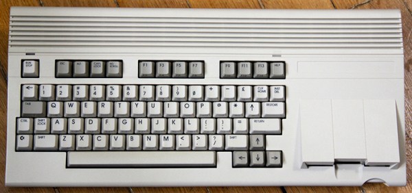
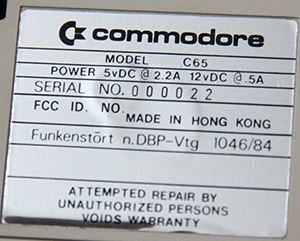 The C65 is not a contemporary of the C64, or even our own [Bil Herd]’s C128. This was the Amiga era, and the C65 was intended to be the last great 8-bit machine.
  The Hackaday Retro Edition is our celebration of old computers doing something modern, in most cases loading


