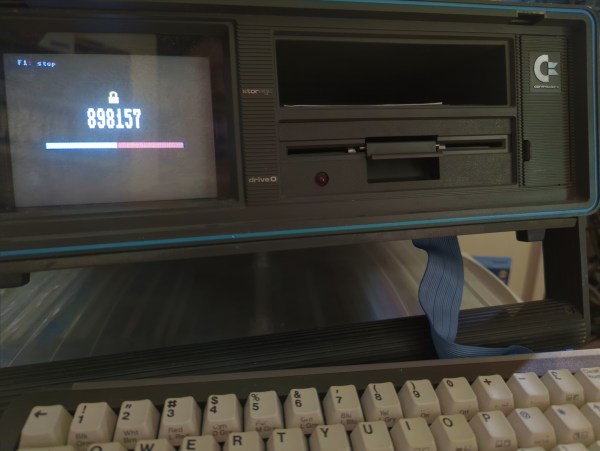
If you’ve used a corporate VPN or an online-banking system in the past fifteen years or so, chances are you’ve got a few of those little authenticator key fobs lying around, still displaying a new code every 30 seconds. Today such one-time codes are typically sent to you by text message or generated by a dedicated smartphone app, which is convenient but a bit boring. If you miss having a dedicated piece of hardware for your login codes, then we’ve got good news for you: [Cameron Kaiser] has managed to turn a Commodore SX-64 into a two-factor authenticator. Unlike a key fob that’s one gadget you’re not likely to lose, and any thief would probably need to spend quite some time figuring out how to operate it. Continue reading “Generating Two-Factor Authentication Codes With A Commodore 64”→
Few things are more satisfying than finding an old, forgotten piece of technology somewhere and bringing it back to life. And while it’s great to see a rare sports car or an Apollo Flight Computer being restored, even not-very-successful game consoles from the 1980s can make for some great repair stories. Just look at how [Discreet Mayor] describes his restoration and modification efforts on a ColecoVision that he literally found in a barn.
Given that the ColecoVision was on the market between 1982 and 1985, we can assume that [Discreet Mayor]’s console had been sitting on a shelf for at least three decades, and the machine was definitely showing its age. Several components had failed due to corrosion, including the clock crystal, a 7400 series logic chip and a capacitor in the power supply, but since these are all standard components it was rather straightforward to replace them.
The controllers however were sadly beyond repair. Replacing them with standard joysticks wasn’t really an option because the ColecoVision controllers included a numeric keypad, which was mainly used to select game options. Making something completely new was the way to go, and [Discreet Mayor] decided to go for a wireless system while he was at it. After all, he had already developed a modular wireless IoT system based on the IEEE 802.15.4 standard, which turned out to be a perfect fit for this system.
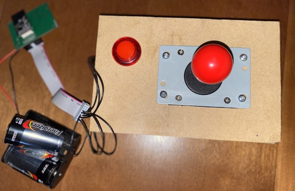
[Discreet Mayor] built a simple joystick-plus-fire-button setup on a piece of MDF and equipped it with his IoT transmitter. Instead of adding a replacement numeric keypad he decided to use the joystick to simulate the most commonly-used buttons: “right” for “1”, “down” for “2” and so on. The receiver module uses digital switches to mimic keypresses to the console’s input port. The end result might look a bit hacky, but the console is fully functional again and runs its games just like it did over thirty years ago.
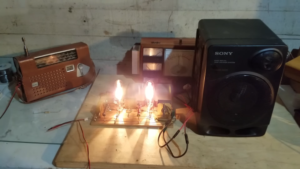
Plugging in something like an antique radio to see if it works is a good way to have a bad time, because some old components don’t age well. For vintage electronics, inspection and repair are steps one and two. When it comes time to cautiously apply power, it’s best to use what’s called a dim-bulb tester and most hackers can probably put one together from scrap.
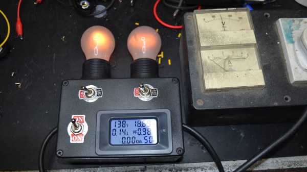
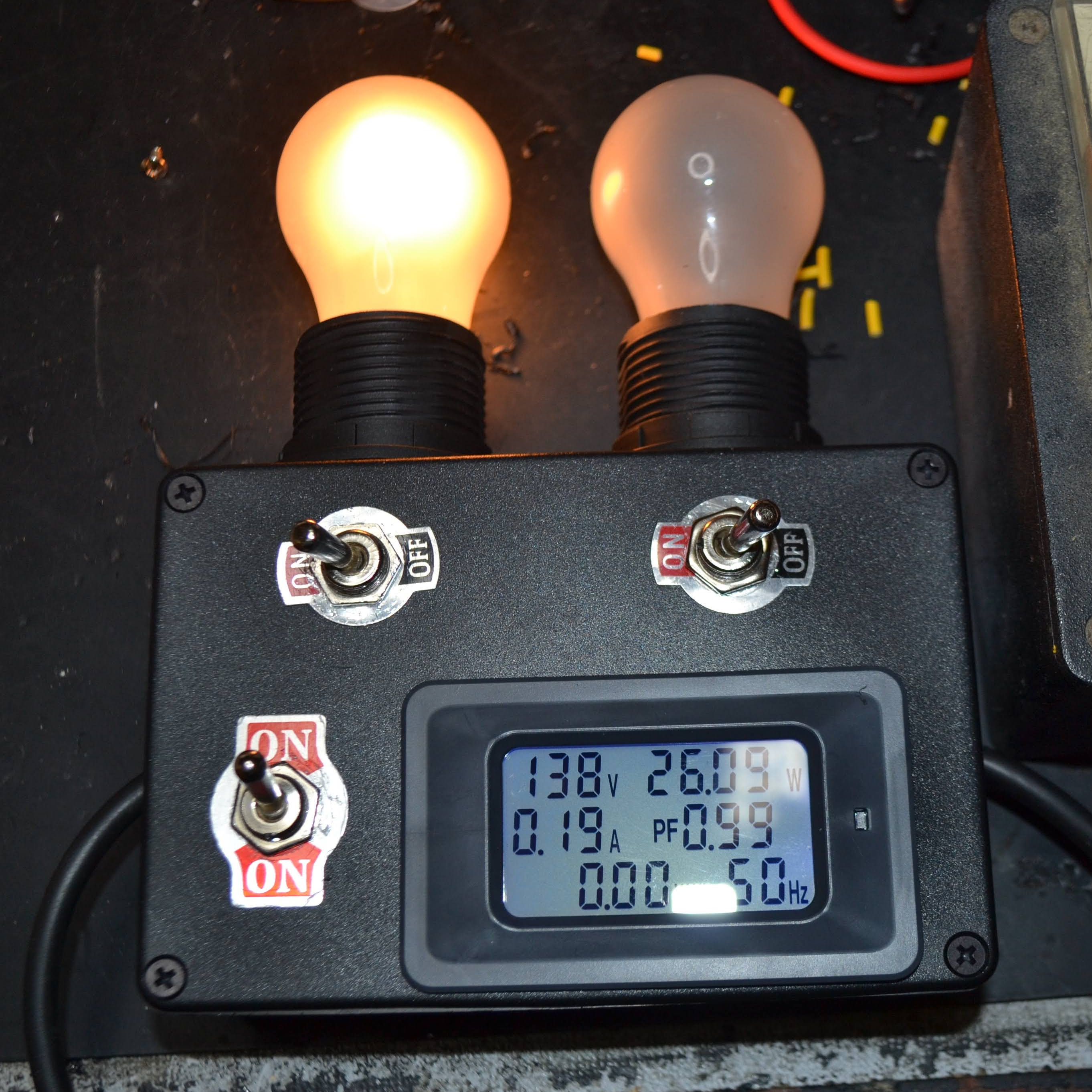
Being able to use one (or both) bulbs adds some flexibility, and the embedded power monitor is an inexpensive and handy addition.
These testers make it easier, and safer, to tell if there are any big problems with a device’s power supply. In its simplest form, a dim-bulb tester puts an incandescent lamp in series between a device — like an old radio — and the AC power from a wall socket. Thanks to this, if the device has a short circuit, the bulb will simply light up instead of causing any damage.
Ideally, one uses a bulb with a wattage rating that is roughly equal to the power consumption of the device being tested. If all is well, the bulb will glow very faintly and the device will work normally. A brightly glowing bulb would indicate excessive current draw. To allow some flexibility, [Doz]’s tester design allows using one or two 60 W incandescent bulbs in series, and even incorporates an inexpensive power monitor.
A dim-bulb tester isn’t an in-depth diagnostic tool but it is effective, simple, and allows for a safe startup even if there’s a serious problem like a short. It helps protect valuable hardware from going up in smoke. In fact, the fundamental concept of limiting power to protect hardware in case of a fault has also been applied in the world of retrocomputing, where it helps protect otherwise irreplaceable hardware if something goes wrong.
Getting DOOM to run on a computer it was never meant to run on is a fun trope in the world of esoteric retro computers. By now we’ve seen it run on everything from old NES systems to microwaves, treadmills, and basically anything with a computer inside of it. What we don’t often see are the displays themselves being set up specifically to run the classic shooter. This build might run the game itself on ordinary hardware, but the impressive part is that it’s able to be displayed on this seven-segment display.
This build makes extensive use of multiplexers to drive enough seven-segment displays to use as a passable screen. There are 1152 seven segment digits arranged in a 48 by 24 array, powered by a network of daisy-chained MAX7219 chips. A Python script running on a Raspberry Pi correlates actual image data with the digit to be displayed on each of the segments, and the Raspberry Pi sends all of that information out to the screen. The final result is a display that’s fast enough and accurate enough to play DOOM in a truly unique way.
There is much more information available about this project on their project page, and they have made everything open source for those who wish to follow along as well. The project includes more than just the ability to play DOOM, too. There’s a built-in video player and a few arcade programs programmed specifically to make use of this display. Perhaps one day we will also see something like this ported to sixteen-segment displays instead of the more common seven-segment.
With the wealth of cheap and highly integrated audio amplifier modules on the market today, it takes a special dedication to roll your own from parts. Especially when those parts include vacuum tubes, and doubly so when you make the vacuum tubes from scratch too.
Now, we get it — some readers are going to find it hard to invest an hour in watching [jdflyback] make a pair of triodes to build his amplifier. But really, you’ve got to check this out. Making vacuum tubes with all the proper equipment — glassblower’s lathe, various kinds of oxy-fuel torches, all the right hand tools — is hard enough. But when your lathe is a cordless drill, and you’re using a spot welder that looks like it’s cobbled together from junk, your tube-making game gets a lot harder. Given all that, you’d expect the tubes to look a lot rougher than they are, but even with plain tungsten wire heaters and grids made from thick copper wire, they actually work pretty well. Sure, the heaters glow as bright as light bulbs, but that’s all part of the charm.
Speaking of charm, we just love the amp these tubes went into. Built in 1920s breadboard-style, the features some beautiful vintage mica capacitors and wirewound resistors, plus a variable resistor the likes of which we’ve never seen. The one nod to modernity is the clever use of doorbell transformers, one for a choke and one for the speaker transformer. They don’t sound great, but there’s no doubt they work.
We may have seen other homemade vacuum tubes before — we even recently featured a DIY X-ray tube — but there’s something about [jdflyback]’s tubes that really gets us going.
Anybody born before the mid 1990s will likely remember film cameras being used to document their early years. Although the convenience of digital cameras took over and were then themselves largely usurped by mobile phones, there is still a surprising variety of photographic film being produced. Despite the long pedigree, how many of us really know what goes into making what is a surprisingly complex and exacting product? [Destin] from SmarterEveryDay has been to Rochester, NY to find out for himself and you can see the second in a series of three hour-long videos shedding light on what is normally the strictly lights-out operation of film-coating.
Kodak’s first attempt at a digital camera in 1975. The form-factor still left something to be desired…
Kodak have been around in one form or another since 1888, and have been producing photographic film since 1889. Around the turn of the Millennium, it looked as though digital photography (which Kodak invented but failed to significantly capitalize on) would kill off film for good, and in 2012 Kodak even went into Chapter 11 bankruptcy, which gave it time to reorganize the business.
They dramatically downsized their film production to meet what they considered to be the future demand, but in a twist of fortunes, sales have surged in the last five years after a long decline. So much so, in fact, that Kodak have gradually grown from running a single shift five days per week a few years ago, to a 24/7 operation now. They recently hired 300 Film Technicians and are still recruiting for more, to meet the double-digit annual growth in demand.
[Destin] goes to great lengths to explain the process, including making a 3D model of the film factory, to better visualize the facility, and lots of helpful animations. The sheer number of steps is mind-boggling, especially when you consider the precision required at every step and the fact that the factory runs continuously… in the dark, and is around a mile-long from start to finish. It’s astonishing to think that this process (albeit at much lower volumes, and with many fewer layers) was originally developed before the Wright Brothers’ first powered flight.
The inner orbits of the Hackaday solar system have been vibrating with the announcement of the 2022 Hackaday Supercon badge. The short version of the story is that it’s a “retrocomputer”. But I think that’s somehow selling it short a little bit. The badge really is an introduction to machine language or maybe a programming puzzle, a ton of sweet blinky lights and clicky buttons, and what I think of as a full-stack hacking invitation.
Voja Antonic designed the virtual 4-bit machine that lives inside. What separates this machine from actual old computers is that everything that you might want to learn about its state is broken out to an LED on the front face, from the outputs of the low-level logic elements that compose the ALU to the RAM, to the decoder LEDs that do double-duty as a disassembler. You can see it all, and this makes it an unparalleled learning aid. Or at least it gives you a fighting chance.
So why would you want to learn a made-up machine language from a non-existent CPU? Tom Nardi and I were talking about our experiences on the podcast, and we both agreed that there’s something inexplicably magical about flipping bits, calling the simplest of computer operations into action, and nonetheless making it do your bidding. Or rather, it’s anti-magical, because what’s happening is the stripping away of metaphors and abstractions. Peering not just behind, but right through the curtain. You’re seeing what’s actually happening for once, from the bottom to the top.
As Voja wrote on the silkscreen on the back of the badge itself: “A programmer who has never coded 1s and 0s in machine language is like a child who has never run barefoot on the grass.” It’s not necessary, or maybe even relevant, but learning a complex machine in its entirety is simultaneously grounding and mind-expanding. It is simply an experience that you should have.
This article is part of the Hackaday.com newsletter, delivered every seven days for each of the last 200+ weeks. It also includes our favorite articles from the last seven days that you can see on the web version of the newsletter.
Want this type of article to hit your inbox every Friday morning? You should sign up!