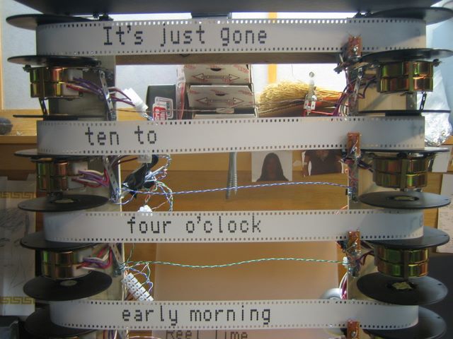
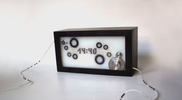
Automatic Daylight Saving Time Compensation For Your Clock Projects

Pretty early in development of my Ping Pong Clock I came up with the idea of automatic Daylight Saving Time compensation. It’s an interesting feature, but it’s a luxury and so I figured I could add it as a future improvement. Now’s the time and I’m reporting back on what I’ve learned and how you can add this to your own projects.

There’s two things to think about before adding this feature. Is it worth the effort and does it make the clock more confusing rather than easier to use?

As to the latter, if you are responsible for setting the time initially but you are not responsible for resetting the clock when we fall back or spring forward will it cause confusion? Perhaps initially, but the battery-backed RTC that I used in my project should mean that you set it once and never have to reset it again. The one exception is DST and that’s what I’m compensating for.

Whether it is worth it or not is difficult to answer until after the fact. You should take into consideration that the DST rules are not set in stone, they change from time to time. Add to that the fact that not all parts of the world observe the practice. This means that not only do you need to implement the compensation, but you should add a method of switching it on and off as well as changing the rules for when it is observed.

Join me after the break to learn the method and code I use to make time adjustments automatically twice a year.

Continue reading “Automatic Daylight Saving Time Compensation For Your Clock Projects”

Glass PCB LED Clock

This clock looks fantastic because of the glass PCB used for the build. This banner image allows you to see all the traces and components, but when it is lifted off of the desk surface the LEDs which make up the 7-segment digits appear to be floating.

The concept isn’t new, but it’s a much larger format than we’ve seen before. When we first looked at [CNLohr’s] glass PCB fabrication he was using microscope slides. This uses a much larger pane of glass but it seems the fabrication still uses copper foil glued to the glass, then toner transfer etched like normal.

Here he’s testing out some 74LV164 chips as constant current drivers. One of the commenters on the Reddit thread is skeptical about using the chip in this way and so are we. But as the video after the break shows, it seems to work (at least for now). [CNLohr] also mentions that the AVR soldered on the display is burnt out which doesn’t help his case. Still, we love the look and can’t wait to see where he goes from here!

Continue reading “Glass PCB LED Clock”

Start Thinking 4th Dimensionally With A Time Circuit Tutorial

When [Phil Burgess] showed off a few I2C – controlled seven-segment displays on adafruit’s weekly vlog, the comments immediately turned to the time circuits featured in everyone’s second-favorite time machine, the Back to the Future DeLorean. The time circuits are now active, so now you can easily add a temporal display to your car well before a hover conversion.

[Phil] used these LED displays, conveniently controlled by a four-wire I2C bus. Although the displays are addressable independently, it’s only possible to assign each display to one of 8 I2C addresses. [Phil] figured out a neat way to control the 9 displays of the time circuit with the help of a 74HC138 3-to-8 line decoder.

The case was constructed out of clear acrylic lasercut in adafruit’s shop and spray painted with faux-metal paint. After installing the seven-segment displays, a Teensy, ChronoDot, and a few AA batteries finished up the build.

With any luck, the design files for the laser cut case should be available shortly, so get those I2C displays while they’re still in stock.

Building A CMOS Clock On A Breadboard

If you’re going to learn digital logic, why not aim high? That’s what [Easton] and his friend did when they built a clock using only 4000-series logic chips. On a breadboard, no less.

For a 1 Hz clock, [Easton] and his friend used a 4060 counter paired with a flip flop. This counts off 59 seconds until, with the help of an AND gate, the seconds counter rolls over to zero. After repeating that again for the minutes and building a similar circuit for the hour, and [Easton] had a working 4000-series 24-hour clock.

The breadboard clock may not be the prettiest thing, or a textbook example of how to prototype circuits,  but that was fixed with [Easton]’s friend’s PCB layout of a 12-hour clock. We couldn’t find any pics of this, but we’re sure it’s awesome and a great way to learn about logic and design.

How Do Atomic Clocks Work?

[Bill Hammack] aka [Engineerguy] is back again with another fantastic informational video. This time around he’s describing exactly how an atomic clock does what it does. He starts off with a great analogy of jello jiggling when poked. He explains how this is similar to the quartz crystal inside the clock oscillating due to the electrical “poke” we give it.  He goes on to explain how GPS satellites rely on this accuracy when determining physical locations on the ground.

As usual, [Bill] does a fantastic job of delivering the information quickly and packed full of detail, while still keeping it simple enough that even those unfamiliar with the technology can follow along.

Continue reading “How Do Atomic Clocks Work?”

Pocketwatch Retrofit Takes Input From Accelerometer

A friend of [CNLohr’s] used the mechanism from an old pocket watch in an art piece, but left him with the enclosure. It’s an interesting looking object that feels great in your hand so he decided to fill it with his own electronics, thereby giving it a new life. He’s showing off an early version of the hardware in the video, but plans to send off another version of the board soon to add a few features.

You can see that the round PCB is small enough to fit in the space vacated by the original hardware. The ribbon cable is used to connect to the programmer and we think it’s also the power source for this demonstration. There’s a small Densitron display that’s reading out hex values from the accelerometer. Many of these mems chip (you can learn how they work from this post) include a hardware tap detector. This meant you can tap your finger on the device and the chip will signal an input to whatever chip is attached to it. That’s a great option for user input, and it’s what [CNLohr] chose as the select button here. He tilts the watch to one side, then taps to turn on the LED. That’s all for now, but we like the promise it shows and can’t wait for updates!

Continue reading “Pocketwatch Retrofit Takes Input From Accelerometer”

Time And Date Clock Does It With RGB LED Strips

[Craig’s] color clock really came together quite nicely. The majority of the body is acrylic, with two large clear squares and a pair of colored discs. All are held in place by a ring of hardware with spacers in them, and the RGB LED strip that is used to display time and date wraps around those spacers. This hides the components in the center, with a USB cord connecting to the Arduino compatible board to power the device.

Hours are displayed in red, with minutes shown in green, and blue used as a background color. In the center you can see one of two red LEDs which alternate like a pendulum to mark the passing seconds. There are timed events every ten , fifteen, and thirty minute. At the fifteen minute mark the clock switches to display the date. The other two events are animations to keep things interesting. All of the settings for the clock are accessed using just two momentary push buttons mounted on the back of the clock.

Continue reading “Time And Date Clock Does It With RGB LED Strips”