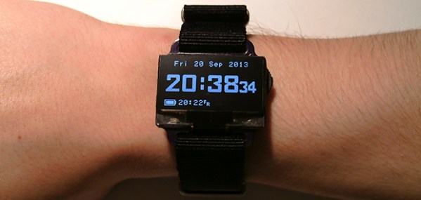
Wristwatch Measures Your Perception Of Time; Also Tells Time

This wristwatch is hiding a lot of features in its hardware and its software. It’s called the TicTocTrac and it’s a Senior project for a pair of students at Cornell University. Judging from the sheer volume and quality of the project documentation we wonder if someone has a science writing career ahead of them? Be we digress… It’s a clock and we love it!

First off, this does more than just tell the time. In fact, that’s almost an ancillary function in this case. The wristwatch is more of a metering device to record your own time-based behaviors. Find yourself checking your watch frequently as the lunch break approaches? This watch records that activity and you can later graph the data. This allows you to analyze how you percieve the passage of time. The more often you check the time, the slower you feel time progressing. The documentation does a much better job of describing this than we have time for, so check it out.

On the hardware side of things we’re quite impressed. The housing is 3D printed. It hides two half-circle PCBs below the full-circle PCB face plate. The half-boards leave space for a tiny rechargeable battery, and host a vibrating motor and RTC chip. Instead of using buttons, there’s a piezo sensor which detects when you tap on the top of the watch.

Six-digit VFD Alarm Clock

[Haris Andrianakis] just finished building this very clean-looking vacuum fluorescent display clock. It shows six digits using IV-11 tubes, and also has a half-dozen RGB LEDs to spice things up (check out the video after the break for an example). An ATmega168 drives the device, controlling the display and serving as a battery-backed real-time clock.

As with any tube-based clock there’s a fair amount of work that goes into driving the display. Each tube has a filament which requires 1.2V, and the segments themselves need 60 volts to light up. The microcontroller is not hard to protect; this is done with a series of transistor-based circuits used for switching. But the need for three voltages (to power microcontroller, filament, and segments) means a more complex PSU design. [Haris] chose to use a MAX6921 to simplify the process.

If you’re considering building something like this, we’d recommend looking for some 12-segment tubes. As we’ve seen before, they can display letters as well as numbers in case you wish to repurpose the device in the future.

Continue reading “Six-digit VFD Alarm Clock”

LED Clock Lights Up A Dead Mac Mini

[Professor Shadoko’s] Mac Mini died. But since the case designs on Apple products are half the reason to buy them, he decided to reuse the enclosure by turning it into this clock (translated).

As with the binary clock we saw yesterday, this one uses a bunch of LEDs to display the time, but it does it in a way that’s a bit more readable if you know what you’re looking for. The face has been divided up into two columns. On the left is hours, then minutes and seconds in increments of five. To the right is AM/PM, with minutes and seconds in increments of one. If we’re doing this right, the time seen above is 10:23:42 PM on April 28th, 2012. The white LEDs below the date act as a digital pendulum, scrolling left and right as the seconds tick by.

The display uses two MAX7219 LED drivers to control the grid which is build on a big hunk of protoboard. An Arduino ties the whole system together with a Chonodot for accurate time keeping. There’s even an ambient light sensor which adjusts the LED intensity to make this readable in direct sun, or the dark of night. See a demo clip embedded after the break.

Continue reading “LED Clock Lights Up A Dead Mac Mini”

A Novel Binary Clock From Hackaday’s Own

Hackaday’s very own [Mike Szczys] just shared an awesome binary clock he’s been working on. Unlike a normal binary clock that is only readable by self-admitted geeks and nerds, [Mike]’s clock is nearly comprehensible by the general population.

There are 12 lines of three LEDs around the face of [Mike]’s clock. These LEDs represent the time in minutes in binary – the inner LED is 1, the middle LED is 2, and the outer LED is 4. Adding up each of the LEDs around the clock face gives the number of minutes passed since the top of the hour.

To display the hour, [Mike] used a red/blue bi-color LED in the center of each line of LEDs. For example, at 1:03 the one ‘o clock hand will have a blue LED in the first position and a purple LED in the second position. A minute later at 1:04, this changes to blue, red, blue.

If that is a little confusing, there’s a wonderful video demonstrating the pattern of LEDs throughout the hour.

For such an interesting clock, the build is fairly simple – just an ATtiny44 with an STP16CP05 LED driver. Time is kept with a battery-backed MCP7940 real-time clock, and power is provided by a simple USB port.

[Mike] had enough boards manufactured for several dozen clocks, but only had enough parts (and patience) to solder up four clocks. You can check out the time-lapse of him going to town with a soldering iron on one of these boards after the break. As with all good builds, the code and schematics are provided on GitHub if you’d like to make your own.

Continue reading “A Novel Binary Clock From Hackaday’s Own”

Mechanical CPU Clock Is Just As Confusing As Its Namesake

[Lior Elazary] designed and built this clock to simulate the function of a CPU. The problem is that if you don’t already have a good grasp of how a CPU works we think this clock will be hopelessly confusing. But lucky for us, we get it, and we love it!

Hour data is shown as a binary number on Register A. This is the center column of red parts and is organized with the MSB on the bottom, the LSB on the top, and left-pointing bits function as digital 1. The clock lacks the complexity necessary for displaying any other time data. But that’s okay, because the sound made by the ball-bearing dropping every minute might drive you a bit loony anyway. [Lior] doesn’t talk about the mechanism that transports that ball bearing, but you can see from the video after the break that a magnet on a circular path picks it up and transports it to the top of the clock where gravity is used to feed the registers. There are two tracks which allow the ball to bypass the A register and enter the B register to the right. This works in conjunction with register C (on the left) to reset the hours when the count is greater than 11.

If you need a kickstart on how these mechanical adders are put together, check out this wooden adder project.

Continue reading “Mechanical CPU Clock Is Just As Confusing As Its Namesake”

A Glorious Mechanical Seven Segment Display

If you’ve ever wondered why you’ve never seen a mechanical seven-segment display, now you know. They’re fairly complicated and most likely absurdly expensive, especially when a few light bulbs or LEDs would do the same job equally well. This didn’t stop [kiu] from completing his mechanical seven-segment clock he calls SevenBlocks, and for that we are thankful.

Each of the 28 segments in [kiu]’s clock is made of three layers of acrylic and a short section of a rack gear. Unlike every seven-segment display you’ve ever seen, tiny hobby servos provide the indication for each segment. For the electronics, An ATMega8 is used for the brains of the outfit with a 74HC595 shift register to expand the number of I/O lines. A DS1307 RTC module provides accurate timekeeping, and the dozens of servo outputs visible in the ‘guts shot’ makes you realize why you’ve never seen a mechanical seven segment display before – they’re really friggin’ complex.

If you want to build your own mechanical seven-segment clock, [kiu] put all the files up on Github. Everything is there, from the .DXF files ready to feed to a laser cutter to the schematic and board files for each of the three PCBs. A video showing this clock in action is sort of necessary, so you can check that out after the break.

Continue reading “A Glorious Mechanical Seven Segment Display”

Building A Game Clock For Go Or Chess

[Matias] is just getting into hobby electronics and decided to push the limits of his skill by building this game clock (site dead try Internet Archive). He comes from a software design background and that really shows through in the UI design seen in the video after the break. We enjoy the journey through his prototyping process which started with an Arduino and a breadboard, and ended with this standalone timer.

After building the first working prototype with four buttons and a character LCD, he migrated to a plastic ice cream container as an enclosure. This worked well enough, but the flimsy case needed an upgrade. As he looked toward the next version he decided to move to an Arduino Nano board to save on space. The rest of the components were soldered to some protoboard, with a pair of pin headers to receive the Nano. The finished board is the same length as the Nano and only about twice as wide.

The box was modeled on the computer (it looks like SketchUp to us be we could be wrong) then cut from pieces of Masonite. It hosts the character LCD with a pair of arcade buttons for each player to shift the time burden to his or her opponent. The middle button pauses the game, and there’s a trimpot on the back to adjust the screen contrast. [Matias] managed to include a surprising number of settings which will make this little box useful for a wide range of game types.

Continue reading “Building A Game Clock For Go Or Chess”