An Alarm For Every Day Of The Week

If you don’t have a 9-to-5 type of job you might find yourself constantly resetting your alarm clock as your calendar commitments change. [Lucas] finally got fed up with the nightly ritual and decided to build his own alarm clock which has unique settings for each day of the week (translated).

The display itself is an LM044L 20×4 character display. This provides a viewing area that is about 3″x1″ and since it’s an HD44780 compliant LCD screen, writing data to it takes very little effort (and RAM) compared to a graphic LCD. A PIC 18F2550 drives the device, taking input from a half-dozen buttons, driving the display, and turning on the enclosed buzzer when it’s time to get up. There’s a backup battery which will keep the settings when power is lost. The daily alarms, current time, and back light brightness can all be adjusted from the four screens that make up the settings menus. The only thing that it’s missing is a precision timekeeper, but that should be easy to add either by measuring the frequency of the mains or by using an RTC chip.

Analog Projection Clock So Simple You Should Have Thought Of It

The image you see above is the result of a simple analog projection clock. It shows the time on the ceiling. We have one in our bedroom but it’s a red digital display which we don’t think is nearly as fun as this clever hack. Grab a cheap analog clock, a mirror, and a white LED and you can build your own.

The mirror is going to reflect light from the LED onto a ceiling or other surface. It acts as the clock face. The tick marks for each hour were made by scratching the reflective material (often called the silvering) from the back of the mirror. A hole is drilled at the center of the class and the analog clock is mounted with its hands on the business side. The one problem with this setup is that since the light is being reflected, the clock will appear to run backwards. Not a problem, if you just reverse the polarity of the coil which moves the clockwork the projection will move in the expected clockwise direction.

[via Make]

DIY Sunrise Alarm Clock

sunrise_alarm_clock

As a project for an embedded systems class, [Alan] recently built himself a sunrise-simulating alarm clock. You are probably familiar with these sorts of timepieces – they gradually light up the room to awaken the sleeping individual rather than jarring them awake with a buzzer or the radio. Since many commercial units with this feature are sold for $70 and up, his goal was to replicate the functionality at a fraction of the cost, using only open source components.

An Arm Cortex M3 processor runs the show, displaying the time via a pair of 8×8 LED matrix panels on the front of the device. The clock is programmed to gently wake up its user by simulating a sunrise over a period of 5, 15, 30, 45, or 60 minutes. If the user has not woken up before the sunrise simulation is complete, the clock resorts to a traditional piezo alarm to rouse the heavy sleeper.

The project is nicely done, and after looking at his bill of materials it seems to be far cheaper than many sunrise alarm clocks you will find in stores.

Egg Clock (it’s Egg-ceptional)

Easter is over and with some plastic eggs still on hand, [Franspaco] was looking for something to do with them. He decided to use an egg as an enclosure for a digital clock.

You can see that the finished project uses just one 7 segment LED display to show the time. A scrolling number method is used to delineate each digit of the 24-hour time readout. The display will go blank, followed by two numbers for the hours, a dash as a separator, and finally two more digits for the minutes. A PICAXE microcontroller drives the clock, but for accuracy a DS1307 does the timekeeping.

[Franspaco] etched his own circuit board that is sized to fit perfectly, housing the two chips, an LED, and a programming header. The on-board LED blinks at 1 Hz, giving some inner glow to the plastic shell. He accomplished most of his goals, but was unable to fit the batteries inside of one egg, prompting the need for a tethered power-egg. If he moves to surface mount components for the next generation of this device we think he’ll have no problem fitting a small battery (like an A23) inside.

Watch Hacking, One Day At A Time

watch_a_day

If there is one thing hackers return to time and time again, it is clock/watch hacking. There are always creative ways to tell time, and with several “hackable” wristwatches on the market, there is bound to be no shortage of neat timepiece hacks.

[hudson] from NYC Resistor has decided to take on a fun challenge for the next month revolving around his programmable inPulse watch. Over the upcoming 30 27 days, he will design, program, and publish a watch face for the timepiece. He already has 3 days behind him, and the results are pretty interesting. The concepts are creative and functional, though due to time constraints they sometimes end up a little less polished than he would like.

All of the code is available on his Bitbucket page if you have an inPulse watch and would like to play along or improve on his work.

We think it’s a pretty cool project, and we are eager to see what he produces each day. Stick around to see a quick video showing off one of his 3D watch faces.

Continue reading “Watch Hacking, One Day At A Time”

flipflop_clock

FlipFlop Clock Uses Mains Frequency To Keep Time

One afternoon, [Sam] was a bit bored and decided he would build a clock. Not wanting to spend any money on the project, he set off to construct his clock using only the components he had on hand – this meant no micro controllers would be used whatsoever.

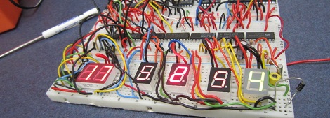
Built on a set of four breadboards, his clock sports a pretty short parts list. It uses just over a dozen flipflops, a few NAND chips, a 555 timer, and a small handful of other components. What you won’t find on the bill of materials however, is any sort of crystal or real-time clock. Instead of using a separate chip for keeping time, he opted to use the 60hz mains frequency as the basis for his time keeping.

The mains sine wave is passed through a series of frequency dividers to reach a 1/60hz signal, which is used to trigger the clock counters he constructed. The time is displayed on a 4-digit seven segment display, using a pair of multiplexers clocked by a 555 timer.

The clock seems to work nicely, though you have to be pretty well-versed in how the clock was built to set the time. The only means of doing so is to probe into the clock of the digit you are setting while pressing the lone pushbutton mounted on the breadboard.

While we are pretty sure no one will ever mess with his clock’s time, we have to wonder if it blinks on and off like our old VCR when the power goes out.

How Low Can You Go?

That’s exactly what [Kenneth Finnegan] figured out with his original investigation into low powered MSP430-based circuits. He was able to keep a count-up timer running off of 20F worth of capacitors for over 10 weeks. Although quite impressive by its own merit, many people left comments that questioned whether similar results would be seen in a circuit with functionality more advanced than simply incrementing a single digit on an LCD. Well folks, [Kenneth] has stepped it up again with this ultra low power LCD clock.

The biggest challenge in creating this clock was finding an efficient way to drive the 28 LCD segments off of the limited number of pins on his MSP430G2231 chip while still having open pins for button inputs as well. An ICM7211 LCD driver is definitely up for the task (with a few clever modifications to drive the auxiliary characters such as the center colon), but requires 8 pins to drive it. A standard 74HC595 latching shift register brings this number down to a more manageable number of 3 total pins.

Once completed the total current consumption was found to be around 12μA – low enough for a claimed run-time of approximately two and a half years from the 3V 200mAh CR2032 coin cell used. If true, a set of standard AA alkaline cells in series as found in many clocks would run this little circuit for decades.

Stick around for a short video after the break and make sure to check out the original blog entry for schematics and the complete source code!

Continue reading “How Low Can You Go?”