Enormous CNC Router Uses Clever Tricks To Improve Performance

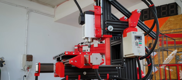
CNC machines made from wood and 3D-printed parts may be popular, but they aren’t always practical from a precision and repeatability standpoint. This is especially true as the machines are scaled up in size, where the compliance of their components starts to really add up. But can those issues be resolved? [jamie clarke] thinks so, and he’s in the process of building a CNC router that can handle a full sheet of plywood. (Video, embedded below.)

This is very much a work in progress, and the videos below are only the very beginning of the process. But we found [jamie]’s build interesting even at this early point because he has included a few clever tricks to control the normal sources of slop that plague larger CNC machines. To provide stiffness on a budget, [jamie] went with a wooden torsion-box design for the bed of his machine. It’s the approach taken by the Root CNC project, which is the inspiration for this build. The bed is formed from shallow boxes that achieve their stiffness through stressed skins applied to rigid, lightweight frames.

Upon the torsion-box bed are guide rails made from commodity lengths of square steel tubing. Stiff these may be over short lengths, but over the three meters needed to access a full sheet of plywood, even steel will bend. [jamie]’s solution is a support that moves along with the carriage, which halves the unsupported length of the beam at all points of travel. He’s using a similar approach to fight whip in the ball screw, with a clever flip-down cradle at the midpoint of the screw.

So far, we’re impressed by the quality of this build. We’re looking forward to seeing where this goes and how well the machine performs, so we’re paying close attention to the playlist for updates. At an estimated build cost of £1,500, this might be just the CNC build you’ve been looking for.

Continue reading “Enormous CNC Router Uses Clever Tricks To Improve Performance”

How Much Is Too Much?

I definitely tend towards minimalism in my personal projects. That often translates into getting stuff done with the smallest number of parts, or the cheapest parts, or the lowest tech. Oddly enough that doesn’t extend to getting the project done in the minimum amount of time, which is a resource no less valuable than money or silicon. The overkill road is often the smoothest road, but I’ll make the case for taking the rocky, muddy path. (At least sometimes.)

There are a bunch of great designs for CNC hot-wire foam cutters out there, and they range from the hacky to the ridiculously over-engineered, with probably most of them falling into the latter pile. Many of the machines you’ll see borrow heavily from their nearest cousins, the CNC mill or the 3D printer, and sport hardened steel rails or ballscrews and are constructed out of thick MDF or even aluminum plates.

All a CNC foam cutter needs to do is hold a little bit of tension on a wire that gets hot, and pass it slowly and accurately through a block of foam, which obligingly melts out of the way. The wire moves slowly, so the frame doesn’t need to handle the acceleration of a 3D printer head, and it faces almost no load so it doesn’t need any of the beefy drives and ways of the CNC mill. But the mechanics of the mill and printer are so well worked out that most makers don’t feel the need to minimize, simply build what they already know, and thereby save time. They build a machine strong enough to carry a small child instead of a 60 cm length of 0.4 mm wire that weighs less than a bird’s feather.

I took the opposite approach, building as light and as minimal as possible from the ground up. (Which is why my machine still isn’t finished yet!) By building too little, too wobbly, or simply too janky, I’ve gotten to see what the advantages of the more robust designs are. Had I started out with an infinite supply of v-slot rail and ballscrews, I wouldn’t have found out that they’re overkill, but if I had started out with a frame that resisted pulling inwards a little bit more, I would be done by now.

Overbuilding is expedient, but it’s also a one-way street. Once you have the gilded version of the machine up and running, there’s little incentive to reduce the cost or complexity of the thing; it’s working and the money is already spent. But when your machine doesn’t quite work well enough yet, it’s easy enough to tell what needs improving, as well as what doesn’t. Overkill is the path of getting it done fast, while iterated failure and improvement is the path of learning along the way. And when it’s done, I’ll have a good story to tell. Or at least that’s what I’m saying to myself as I wait for my third rail-holder block to finish printing.

3D Finger Joints For Your Laser Cutter

A laser cutter is an incredibly useful tool and they are often found in maker spaces all over. They’re quite good at creating large two-dimensional objects and by cutting multiple flat shapes that connect together you can assemble a three-dimensional object. This is easier when creating something like a box with regular 90-degree angles but quickly becomes quite tricky when you are trying to construct any sort of irregular surface. [Tuomas Lukka] set out to create a dollhouse for his daughter using the laser cutter at his local hackerspace and the idea of creating all the joints manually was discouraging.

The solution that he landed on was writing a python script called Plycutter that can take in an STL file and output a series of DXF files needed by the cutter. It does the hard work of deciding how to cut out all those oddball joints.

At its core, the system is just a 3D slicer like you’d find for a 3D printer, but not all the slices are horizontal. Things get tricky if more than two pieces meet. [Tuomas] ran into a few issues along the way with floating-point round-off and after a few rewrites, he had a fantastic system that reliably produced great results. The dollhouse was constructed much to his daughter’s delight.

All the code for Plycutter is on GitHub. We’ve seen a similar technique that adds slots, finger-joints, and t-slots to boxes, but Plycutter really offers some unique capabilities.

CNC Router Frame Repurposed For Colorful String Art Bot

Pandemic lockdowns have been brutal, but they’ve had the side-effect of spurring creativity and undertaking projects that are involved enough and complex enough to keep from going stir crazy. This CNC string art robot is a great example of what’s possible with a little imagination and a lot of time. (Video, embedded below.)

According to [knezuld11], the robot creates its art through mathematical algorithms via a Python program that translates them into nail positions and string paths. The modified CNC router frame, constructed of laser-cut plywood, has two interchangeable tool heads. The first places the nails, which are held in a small hopper. After being picked up by a servo-controlled magnetic arm and held vertically, a gear-driven ram pushes each nail into a board at just the right coordinates. After changing to a different tool, the robot is able to pick up one of nine different thread dispensers. A laser sensor verifies the thread nozzle position, and the thread starts its long journey around the nails. It’s a little mesmerizing to watch, and the art looks great, with a vibe that brings us right back to the 70s. Groovy, man.

This reminds us a little of a recent [Barton Dring] project that makes art from overlapping strings. That one was pretty cool for what it accomplished with just one thread color, while this one really brings color to the party. Take your pick, place your nails, and get stringing.

Continue reading “CNC Router Frame Repurposed For Colorful String Art Bot”

DIY Camera Motion Rig Is Mostly 3D Printed

These days, Youtube is more competitive than ever. Creators put out videos of wildly expensive, complex projects with equally pricy camera gear. [Do It Whenever?] wanted to join the arms race, building his own camera rig for smooth, swooping shots.

The rig consists of a series of 3D printed axes all joined together into a 6-axis motion rig. Additionally, actuators attached to the lens of the camera allow zoom and focus to be be controlled programmatically too. An Arduino runs the show, interpreting G-code and running the various axes, with a Raspberry Pi acting as a gateway to allow the rig to be commanded from PCs or smartphones.

Currently, control is largely manual, by entering G-code commands to move the rig in various ways. The rig can also have its motors temporarily disengaged by a button, allowing the camera to be aimed by hand, before holding the position. In this way, it acts as a highly versatile tripod. Future plans involve more automation if suitable open-source software can be found.

It’s an impressive rig, even if it hasn’t quite found the perfect software to fully exploit its capabilities yet. We’ve seen similar builds before, too. Video after the break.

Continue reading “DIY Camera Motion Rig Is Mostly 3D Printed”

Cutting Balsa Wood With Air (Oh, And A Laser)

[DIY3DTech] likes using his Ortur laser cutter for balsa wood and decided to add an air assist system to it. Some people told him it wasn’t worth the trouble, so in the video below, he compares the results of cutting both with and without the air assist.

The air assist helped clear the cut parts and reduced charring in the wood. The air system clears residue and fumes that can reduce the effectiveness of the laser. It can also reduce the risk of the workpiece catching on fire.

Continue reading “Cutting Balsa Wood With Air (Oh, And A Laser)”

Rotary Plotter Draws On Bottles

A pen plotter is often the first experience many ambitious makers have of the world of Computer Numerical Control, or CNC. While they typically operate on flat stock, with the right build, they can be designed to draw on curved surfaces, too – as [tuenhidiy] demonstrates with this rotary bottle plotter.

The plotter uses shafts salvaged from an old printer to act as the rollers for the bottle to be drawn upon, turned by a pair of stepper motors. X and Z axes are created out of two CD drive mechanisms – a popular way to build two linear axes on the cheap. The hardware is controlled by GRBL, running on an Arduino Uno kitted out with a CNC shield to handle the necessary I/O.

The build is somewhat limited to by the short range of its X axis, which prevents the plotter from easily drawing on a full-size bottle label or can. However, this could easily be fixed with some upgrades and extra steppers if so desired. As a home build, it’s a great way to learn about the CNC techniques required to work with curved surfaces effectively. Video after the break.

Continue reading “Rotary Plotter Draws On Bottles”