An M1 Mac mini sits next to a white Wii on a wooden table. In the background are various Edison-style LED light fixtures with an incadescent-like light profile.

This Wii Has An Apple M1 Inside

The conveniently tiny logic board of the M1 Mac mini has lead to it giving the Mini ITX format a run for its money in case mods. The latest example of this is [Luke Miani]’s M1 Wii. (Youtube via 9to5Mac)

[Miani] chose the Wii as a new enclosure for this Mac mini given its similar form factor and the convenient set of doors in the top to maintain access to the computer’s I/O, something he wasn’t able to do with one of his previous M1 casemods. The completed build is a great stealth way to have a Mac mini in your entertainment center. [Miani] even spends the last several minutes of the video showing the M1 Wii running Wii, GameCube, and PS2 games to really bring it full circle.

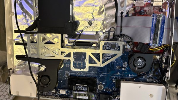
A Microsoft Surface power brick was spliced into the original Wii power cable since the Wii PSU didn’t have enough wattage to supply the Mac mini without significant throttling. On the inside, the power runs through a buck converter before making its way to the logic board. While the Mini’s original fan was too big to fit inside the Wii enclosure, a small 12V fan was able to keep performance similar to OEM and much higher than running the M1 fanless without a heat spreader.

If you’d like to see some more M1 casemods, check out this Lampshade iMac or the Mac Mini Mini.

Continue reading “This Wii Has An Apple M1 Inside”

Commodore Datasette Does Its Own Calibration

Ah, the beloved Commodore 64. The “best-selling computer system of all time”. And hobbyists are keeping the dream alive, still producing software for it today. Which leads us to a problem with using such old equipment. When you get your copy of Petscii Robots on cassette, and try to fastload it, your machine might just consistently fail to load the program. That’s fine, time to pull out the cue-tips and rubbing alcohol, and give the read heads a good cleaning. But what if that doesn’t do the job? You may just have another problem, like tape speed drift.

There are several different ways to measure the current tape speed, to dial it in properly. The best is probably a reference cassette with a known tone. Just connect your frequency counter or digital oscilloscope, and dial in the adjustment pot until your Datasette is producing the expected tone. Oh, you don’t have a frequency counter? Well good news, [Jan Derogee] has a solution for you. See, you already have your Datasette connected to a perfectly serviceable frequency counter — your Commodore computer. He’s put out a free program that counts the pulses coming from the Datasette in a second. So play a reference cassette, run the program, and dial in your Datasette deck. Simple! Stick around after the break for a very tongue-in-cheek demonstration of the problem and solution.

Continue reading “Commodore Datasette Does Its Own Calibration”

Four M.2 cards of different sizes on a desk surface

M.2 For Hackers – Cards

Last time, I’ve explained everything you could want to know if you wanted to put an M.2 socket onto your board. Today, let’s build M.2 cards! There’s a myriad of M.2 sockets out there that are just asking for a special card to be inserted into it, and perhaps, it’s going to be your creation that fits.

Why Build Cards?

Laptops and other x86 mainboards often come with M.2 slots. Do you have a free B-key slot? You can put a RP2040 and bunch of sensors on a B-key PCB as an experimental platform carried safely inside your laptop. Would you like to do some more advanced FPGA experiments? Here’s a miniscule FPGA board that fits inside your laptop and lets you play with PCIe on this same laptop – the entire setup having a super low footprint. Are you looking for an extra PCIe link because you’re reusing your laptop as a home server? Again, your WiFi slot will provide you with that. Want to get some PCIe out of a SteamDeck? Building a M-key 2230 card seems to be your only hope! Continue reading “M.2 For Hackers – Cards”

M.2 For Hackers – Connectors

In the first M.2 article, I’ve described real-world types and usecases of M.2 devices, so that you don’t get confused when dealing with various cards and ports available out there. I’ve also designed quite a few M.2 cards and card-accepting adapters myself. And today, I’d like to tell you everything you need to know in order to build M.2 tech on your own.

There’s two sides to building with M.2 – adding M.2 sockets onto your PCBs, and building the PCBs that are M.2 cards. I’ll cover both of these, starting with the former, and knowing how to deal with M.2 sockets might be the only thing you ever need. Apart from what I’ll be describing, there’s some decent guides you can learn bits and pieces from, like the Sparkfun MicroMod design guide, most of which is MicroMod-specific but includes quite a few M.2 tips and tricks too.

First, Let’s Talk About The Y-Key

What could you do with a M.2 socket on your PCB? For a start, many tasty hobbyist-friendly SoMs and CPUs now have a PCIe interface accessible, and if you’re building a development board or a simple breakout, an M.2 socket will let you connect an NVMe SSD for all your high-speed low-power storage needs – many Raspberry Pi Compute Module mainboards have M.2 M-key sockets specifically for that, and there’s NVMe support in the RPi firmware to boot. Plus, you can always plug a full-sized PCIe adapter or an extender into such a socket and connect a PCIe network card or other much-needed device – even perhaps, an external GPU! However, as much as PCIe-equipped SoMs are tasty, they’re far from the only reason to use M.2 sockets.

Continue reading “M.2 For Hackers – Connectors”

Bye Bye Linux On The 486. Will We Miss You?

A footnote in the week’s technology news came from Linus Torvalds, as he floated the idea of abandoning support for the Intel 80486 architecture in a Linux kernel mailing list post. That an old and little-used architecture might be abandoned should come as no surprise, it’s a decade since the same fate was meted out to Linux’s first platform, the 80386. The 486 line may be long-dead on the desktop, but since they are not entirely gone from the embedded space and remain a favourite among the retrocomputer crowd it’s worth taking a minute to examine what consequences if any there might be from this move.

Is A 486 Even Still A Thing?

Block diagram of the ZFx86 SoC
An entire 486 PC in a chip that only uses 1W, that would have been amazing in 1994!

The Intel 80486 was released in 1989, and was substantially an improved version of their previous 80386 line of 32-bit microprocessors with an on-chip cache, more efficient pipelining, and a built-in mathematical co-processor. It had a 32-bit address space, though in practice the RAM and motherboard constraints of the 1990s meant that a typical 486 system would have RAM in megabyte quantities. There were a range of versions in clock speeds from 16 MHz to 100 MHz over its lifetime, and a low-end “SX” range with the co-processor disabled. It would have been the object of desire as a processor on which to run WIndows 3.1 and it remained a competent platform for Windows 95, but by the end of the ’90s its days on the desktop were over. Intel continued the line as an embedded processor range into the 2000s, finally pulling the plug in 2007. The 486 story was by no means over though, as a range of competitors had produced their own take on the 486 throughout its active lifetime. The non-Intel 486 chips have outlived the originals, and even today in 2022 there is more than one company making 486-compatible devices. RDC produce a range of RISC SoCs that run 486 code, and according to the ZF Micro Solutions website they still boast of an SoC that is a descendant of the Cyrix 486 range. There is some confusion online as to whether DM&P’s Vortex86 line are also 486 derivatives, however we understand them to be descendants of Rise Technology’s Pentium clone. Continue reading “Bye Bye Linux On The 486. Will We Miss You?”

The SSD described, a green board with a ZIP connector, a controller chip and two out of four NAND chips populated. There's traces of flux on the chip, as it hasn't been washed after soldering yet.

ZIF HDDs Dying Out? Here’s An Open-Source 1.8″ SSD

A lot of old technology runs on parts no longer produced – HDDs happen to be one such part, with IDE drives specifically being long out of vogue, and going extinct to natural causes. There’s substitutes, but quite a few of them are either wonky or require expensive storage medium. Now, [dosdude1] has turned his attention to 1.8 ZIF IDE SSDs – FFC-connected hard drives that are particularly rare and therefore expensive to replace, found in laptops like the Macbook Air 1,1 2008 model. Unsatisfied with substitutes, he’s designed an entire SSD from the ground up around an IDE SSD controller and NAND chips. Then, he made the design open-source and filmed an assembly video so that we can build our own. Take a look, we’ve put it below the break!

For an open-source design, there’s a respectable amount of work shared with us. He’s reverse-engineered some IDE SSDs based on the SM2236 controller to design the schematic, and put the full KiCad files on GitHub. In the video, he shows us how to assemble this SSD using only a hot air station and a soldering iron, talks about NAND matching and programming software intricacies, and shows the SSD working in the aforementioned Macbook Air. Certainly, assembly would have been faster and easier with a stencil, but the tools used work great for what’s a self-assembly tutorial!

Continue reading “ZIF HDDs Dying Out? Here’s An Open-Source 1.8″ SSD”

showing the connector after its torn down from the side of the wire solder points, showing how thin are the metal pads, and also that one wire has already broken off

NVIDIA Power Cables Are Melting, This May Be Why

NVIDIA has recently released their lineup of 40-series graphics cards, with a novel generation of power connectors called 12VHPWR. See, the previous-generation 8-pin connectors were no longer enough to satiate the GPU’s hunger. Once cards started getting into the hands of users, surprisingly, we began seeing pictures of melted 12VHPWR plugs and sockets online — specifically, involving ATX 8-pin GPU power to 12VHPWR adapters that NVIDIA provided with their cards.

Now, [Igor Wallossek] of igor’sLAB proposes a theory about what’s going on, with convincing teardown pictures to back it up. After an unscheduled release of plastic-scented magic smoke, one of the NVIDIA-provided connectors was destructively disassembled. Turned out that these connectors weren’t crimped like we’re used to, but instead, the connectors had flat metal pads meant for wires to solder on. For power-carrying connectors, there are good reasons this isn’t the norm. That said, you can make it work, but chances are not in favor of this specific one.

The metal pads in question seem to be far too thin and structurally unsound, as one can readily spot, their cross-section is dwarfed by the cross-section of cables soldered to them. This would create a segment of increased resistance and heat loss, exacerbated by any flexing of the thick and unwieldy cabling. Due to the metal being so thin, the stress points seem quite flimsy, as one of the metal pads straight up broke off during disassembly of the connector.

If this theory is true, the situation is a blunder to blame on NVIDIA. On the upside, the 12VHPWR standard itself seems to be viable, as there are examples of PSUs with native 12HPWR connections that don’t exhibit this problem. It seems, gamers with top-of-the-line GPUs can now empathize with the problems that we hackers have been seeing in very cheap 3D printers.