New IOIO Is Faster, Cheaper

board-nobg

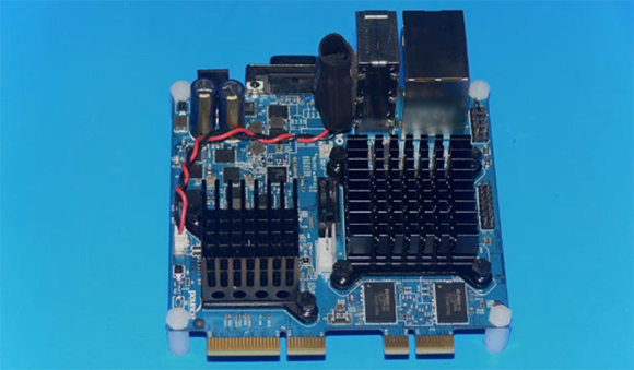
For the last few years, [Ytai] has been working on the IOIO, a device that connects your Android devices to the other homebrew peripherals. There’s a new version of this really cool board out now that includes a few much-needed features like USB-OTG and a lower component cost that is passed on in savings to you.

A few months ago, our own [Mike Szczys] caught a glimpse of this new IOIO board. It’s the same size as the previous revision, but with USB-OTG, the new IOIO can be a master when connected to a phone, or a slave when connected to a PC.

In addition to USB-OTG, [Ytai] improved the power regulation circuit, and even went so far as to refuse royalties to the board to get the costs down. It’s currently available at Sparkfun for $40.

[Ytai] says he’s working on a few software upgrades to the IOIO, including making capacitive sensing a possibility and including support for stepper motors and controllers. There’s also support for the Raspberry Pi coming up, but we’re just glad [Ytai] managed to put a yo-yo graphic on the bottom silkscreen. Finally, and hopefully, everyone will know how to pronounce IOIO.

Stuffing An NES Into An FPGA

megaman_fpga

When the developer of the µTorrent torrent client and the ScummVM  LucasArts adventure game interpreter gets bored, something cool is bound to happen. Luckily for us, [Ludde] was a bit listless over Christmas, and with more time than energy to burn, implemented a Nintendo Entertainment System on an FPGA dev board.

The NES was powered by a Ricoh 2A03 CPU, a chip nearly identical to the 6502 found in the Commodore 64s and Apple IIs of the early 1980s. There are a few differences between the two, though: the NES CPU includes an Audio Processing Unit on the chip and is connected to a very cool Picture Processing unit elsewhere on the NES. [Ludde] put all these chips in his Spartan-6 FPGA with a lot of Verilog code.

The rest of the system – the RAM, display output, and controller input comes from the peripherals attached to the FPGA dev board. [Ludde]’s specific board didn’t have a good digital to analog converter, so the composite output was traded for a VGA output. It’s not a completely accurate color pallet, but it’s still an amazing piece of work for someone who was simply bored.

Custom Gauges With A Stepper Motor Breakout Board

Throw some blinking LEDs on a project and it’s bound to make the front page of Hackaday. We do love builds of a more analog character, though, and this analog gauge stepper motor breakout board seems like just the ticket to make those projects a reality.

The idea behind the project is simple: take a stepper motor, put a needle on it, and connect it to an Arduino. Instant analog gauge, measuring anything an Arduino can calculate.

The motor used in the build is a Switec X27.168, the same motor used in the dashboard of tens of thousands of automobiles from dozens of different makes and models. Controlling the motors is done through [Guy Carpenter]’s Switec X25 library for the Arduino, allowing an Arduino Uno to control up to three stepper motor gauges simultaneously.

The movement of the needle is amazingly smooth and quite fast, as seen in the video after the break. A pretty cool piece of kit if you want a more analog display than LEDs and LCDs can provide.

Continue reading “Custom Gauges With A Stepper Motor Breakout Board”

Breathing Life Into An Old LCD

panel

Out of the depths of a junk drawer, [Alex]’s friend pulled out an old monochrome LCD display. This is an older low-resolution display from ancient electronics that unfortunately doesn’t have its own controller chip. No worries, though, because with the help of an FPGA [Alex] figured out how to drive this display.

On the back of this display are eight Hitachi LCD drivers, six column shifters and two row shifters, allowing the LCD to display a 256×128 pixel image. Without an LCD controller, though, [Alex] couldn’t just send a static image to the LCD. Instead, he had to continuously refresh the display just like a VGA monitor.

With the help of a 1500-page PDF titled Hitachi LCD Controller/Driver LSI Data Book, [Alex] was able to dump pixels into the ICs on the display with the help of a Papilio One FPGA board. A lot of work just to display the beautiful [Lena], but she wouldn’t have it any other way.

Raspi Astrophotography Board Also Does Everything Else

FPGA

A few years ago the folks at Astro Designs put together a board that took off-the-shelf CCD sensors from point and shoot cameras and turned them into respectable astrophotography sensors. Since then, the world has seen an explosion of Raspberry Pis, Arduinos, and other microcontroller platforms, making this the perfect time for a hardware revision.

Their PiXi-200, like their previous AstroCam board, is able to take image sensors out of cameras and turn them into telescope mounted cameras. That’s only one of its tricks, though: The PiXi-200 also has accelerometers, gyroscopes, enough UARTs to do just about anything, a four channel ADC and four channel DAC, two dozen GPIO pins, enough LEDs and buttons for any project, and a 200,000 gate FPGA. All this in a board that plugs directly into the GPIO pins on the Raspberry Pi just like an Arduino shield. Needless to say, there’s a lot you can do with this board.

Right now, the design is still in the prototype stage, but once everything is finalized the basic model of the board will sell for £30 GBP ($50 USD). The high-end “Model C” board, with all the bells and whistles, will sell for £45 GPB ($70 USD).

USB To Serial Adapter Tells You What COM Port You’re On

xser

Since most of us are long past the days of hardware serial ports, the USB to serial adapter has become a mainstay on the hacker’s tool belt. While they’re cheap and convenient, USB to serial adapters aren’t always the easiest thing to use: there’s always the issue of what COM port Windows is calling your USB to serial adapter, or what TTY device it is in Linux/OS X.

[Avishay] has a very, very cool solution to this problem: put a display on a USB to serial converter to tell the user what COM port the OS labeled it as.

The prototype runs on a PIC  18F2553 dev board. When plugged into a Windows box, the serial adapter sets up two USB devices. The first device is a Communications Device Class that handles the grunt work of the USB to Serial connection. The second USB device is a proprietary piece of software that grabs the current COM port number. This number is displayed on an LCD thanks to a host application on the Windows PC that reports the COM port of the Serial adapter.

It’s one of those ideas where you didn’t know you needed it until it was presented to you. An excellent tool from [Avishay], although maybe a pair of 7-segment LEDs would make it a more manufacturable device.

[Ben Krasnow] Builds A CT Scanner

gif

After building a homebrew x-ray backscatter imager, [Ben Krasnow] realized he had nearly all the components to build his own CT scanner, able to make a 3D model of the inside of a frozen chicken.

Basically, a CT scanner takes dozens of x-rays of an object and reassembles them with the help of fancy algorithms to allow doctors to peer inside a human body. The CT scanners you’ll find at your local hospital are monstrous devices, rotating an x-ray tube and sensor around a patient with the help of some very heavy duty electromechanical engineering. [Ben] wanted to keep his build rather small, so instead of rotating the x-ray tube and screen around an object, he simply made a stepper motor-driven lazy suzan to rotate his frozen bird.

[Ben] set a digital camera off to the side of his build and captured 45 images of a rotating chicken. After correcting for the perspective distortion, the images were thrown into 3D Slicer to create a true 3D representation of a x-rayed chicken.

Continue reading “[Ben Krasnow] Builds A CT Scanner”