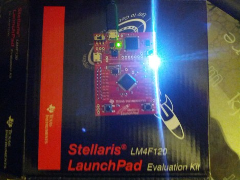
In our last Stellaris how-to we got the board working and set some registers to turn on the LED. This time we’ll start using StellarisWare Driverlib, which provides drivers for the microcontroller’s peripherals including GPIOs, UARTs, ADCs, and so on. These libraries make it easier to control the peripherals. We’ll build the Driverlib project, create a project from scratch to use the library, and run a simple LED blinking example.
how-to902 Articles
Hardware hacking how-tos
Getting Started With The Stellaris Launchpad
We’ve already given an overview of the Stellaris Launchpad, but lets look at the first steps to running code on the device. First we’ll get the development software working, then we’ll build and run a very simple example.
TI allows use of the full version of their IDE, Code Composer Studio, with the Launchpad’s on-board debugger. To work with Stellaris microcontrollers, you’ll also need to grab StellarisWare. This free software package contains support for the Stellaris devices including peripheral drivers, a USB library, and code examples. Finally, you’ll need the ICDI drivers to communicate with the debugger. TI has all the required software for this board available here. See the TI getting started directions for a walk-through of how to install the required software.
Continue reading “Getting Started With The Stellaris Launchpad”
L.I.O.S.: The Ten-ish Dollar Robot.

We love cheap stuff here. Who doesn’t? [Oscar Rodriguez Parra] does too, and wrote in to show us his super cheapey robot L.I.O.S. The build was for the AFRON design challenge, which involves building a 10 dollar robot to teach students robotics. The winners of the challenge were neat and all, but they all look too fancy flaunting their molded plastics and electronics breadboards.
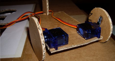
[Oscar’s] design is super simple, LDRs as eyes, a PIC12F683 to do the brainin, LEDs for indicators and a couple modded servos to drive the wheels. An extraordinarily complex cardboard flap roller helps the cart turn, but probably isn’t going to see much aside from smooth flooring. The electronics are mounted using one of our favorite techniques, the paper perf board (very similar to the substrate free technique).
Check out the video after the jump to see LIOS in action. This is an excellent introduction to robotics for any classroom. Thanks [Oscar]!
Test Your Project’s Mettle With A Protected Dummy Load

For a power hungry project the supply is sometimes a pretty big unknown. Whether stapling together a few different power supplies to meet a current requirement, or designing a system from the ground up: a big power supply can be quite a dangerous thing. It helps to have some kind of a dummy load to really shake down the electronics and get an idea of how hot things get or test stability before trusting the supply to run your stuff. [Paulo Oliveira] has constructed just such a thing, a slick looking adjustable constant current load.
Following the popular LM324 circuit from [David Jones] at EEVblog [Paulo] decided to make use of the two spare op-amps to provide both a thermal overload and a cooling fan circuit. We have seen other tweaks to [David]’s circuit in the past but through some resistors and MOSFETs [Paulo] can now load up to 7A (limited by resistor wattage). We would have used a really crazy server vacuum fan to make it genuinely frightening to push heavier loads. Thanks [Paulo]!
Beginner’s Look At On-Chip Debugging
As your embedded applications get more complicated an On-Chip Debugger will save you a lot of time when things don’t run quite right. On-Chip Debugging (OCD) is just what it sounds like — a way to run your program on the target chip that lets you pause execution to examine values and change them if need be. The Arduino has no built-in method of using OCD, but the AVR chips used by the boards do. The caveat is that you need a proper AVR programmer to access the Debug Wire protocol, or a JTAG interface for some of the larger chips. In this case I’m going to be using an STM32 Discovery Board to give you an overview of OCD. But this will work the same way for any chip that has hardware debugging capabilities. Many IDE’s have debugging support built right in so that you can use a nice GUI as you work. But often these are just a front end for the command line tools I’ll be using. Join me after the break and we’ll get started.
Adding Famicom Audio Channles To An NES Without Messing Up The Console

[Callan Brown] wrote in to show us a really interesting NES audio hack. [Callen] decided that he wanted the full Castlevania III audio experience, which (without modifications) can only be had through the original Japanese Famicom console. [Callen] weighed a few adapter options, and instead decided to come up with his own.
The issue is that the Japanese Famicom and the American NES actually have a different cartridge connector. The change in hardware from a 60 pin to a 72 pin connector added “features” like the 10 pins connected directly to the expansion port (used for stuff like the teleplay modem, who knew). The other two additional pins are used by the annoying 10NES lockout chip. While they were at it, Nintendo decided to route the audio path through the expansion connector instead of the cartridge.
This means that the Japanese cartridges can’t pipe sound to the NES audio channel with just a pin adapter. Good news though, after sourcing a pin adapter hidden inside certain NES games (Stack Up, Gyromite), audio can easily just be pulled from the adapter PCB. This requires the more expensive Famicom Castlevania III cartridge (Akumajou Densetsu). To cleanly route the new audio cable out of his front loading NES [Callan] reuses the sacrificial adapter game’s cart to make some kind of unholy hybrid. To round it off [Callan] also goes over steps to flash a translated ROM to the Japanese game.
What difference could an extra two squares and a sawtooth make? Check out the sound comparison video after the jump! Thanks [Callan].
Continue reading “Adding Famicom Audio Channles To An NES Without Messing Up The Console”
Another Eerily Similar High Power LED Driver Hack

[Maximilian Güntner] dropped us a comment in last week’s globe writeup linking to his own project, which involves a similar high power LED driver mod. This looks like the exact same mod we came up with, and [Güntner] even used the mod to connect a bunch of high power LEDs to a PCA9685 LED driver [pdf]. It’s the same exact concept as Disco Planet!
It should come as no surprise that people have actually been modding high power led drivers in this way for some time. They are a few bucks per handful and take an enormous input voltage range. In [Güntner]’s case he grabbed a bunch of these from Dealextreme. Actually there are two others on the site, and all three contain comments (dating back a year) with helpful tips on various ways to modify the little PCB.
Our Ebay sourced boards are different though. The boards [Güntner] purchased employ the PowTech PT4115 [pdf] which uses fewer parts and has an easy to follow data sheet. Take, for instance, the pin graciously labeled “DIM” with a little PWM signal next to it. The nerve! The Ebay drivers use the MCP34063 [pdf] which has a much more cryptic data sheet (burned two weeks and several notebook pages to figure out the circuit). Ultimately the two are so similar it makes no difference.
So, if you want to mod some LED drivers on your own, check out the how-to video after the jump. Thanks [mguentner]!
Continue reading “Another Eerily Similar High Power LED Driver Hack”