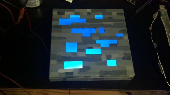
We were surprised to see all of the Christmas gifts that revolved around Minecraft. Seems like there’s a lot of stuff for sale, but we still like the DIY spirit that comes with making your own. [Thacrudd] recently finished this project. It’s a wall lamp that looks like Minecraft’s diamond ore.
The enclosure is a wood box that used to contain chocolates. After studying the pixel art texture for the game’s diamond ore blocks he marked out the pattern and headed over to the scroll to rough them out before finishing with files and a rasp. Next came paint, which was sourced as a sample from the home store. This left him with one shade of gray, but the variations were easy to add by mixing it with white or black.
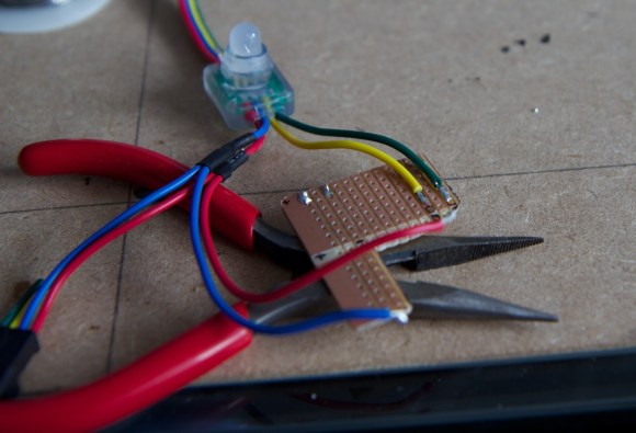
A strip of white LEDs gives the lamp its inner glow. The openings have been covered with blue acrylic which keep the dust out while providing the appropriate hue.
[via Reddit]