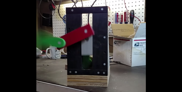
Revive The Demoscene With A LayerOne Demoscene Board

Demos, the demoscene, and all the other offshoots of computer arts had their beginning as intros for cracked Apple II, Speccy, and Commodore 64 games. Give it a few years, and these simple splash screens would evolve into a technological audio-visual experience. This is the birth of the demoscene, where groups of programmers would compete to create the best demonstration of computer graphics and audio.

For one reason or another, this demoscene was mostly confined to Europe; even today, 30 years after the Commodore 64, the North American demoscene is just a fraction of the size of the European scene. A very cool guy named [Arko] would like to change that, and to that end he built the LayerOne Demoscene Board.

If there is a problem with the modern demo scene, it’s that the hardware that’s usually used – C64s, Ataris, Spectrums, and Amigas – are old, somewhat rare, and dying. There’s also the fact that artists have been working on these old machines for decades now, and every single ounce of processing power and software trickery has been squeezed out of these CPUs. [Arko]’s board is a ground-up redesign of what a board that plays demos should be. There’s only one chip on the board – a PIC24F with three graphics acceleration units, color lookup tables, and the ability to output 16-bit VGA video up to 640×480 with 8-bit audio.

The first official competition with the LayerOne Demoscene Board will be at the 2015 LayerOne conference in Monrovia, CA on May 23. There are a few categories, including 4k and 64k JavaScript, Raspberry Pi, the LayerOne board, and a ‘Wild’ category. If you want to take a processor out of a toaster and make a demo, this is the category you’ll be entering. Of course Hackaday will be there, and we’ll be recording all the demos.

Below are a few examples of what the LayerOne Demoscene board can do, and you can also see a talk [Arko] gave at the Hackaday 10th anniversary party here. You can buy the Layerone Demoscene Board on the Hackaday Store

Continue reading “Revive The Demoscene With A LayerOne Demoscene Board”

Deconstructing PCBs

The surest way to reverse engineer a circuit is to look at all the components, all the traces between these components, and clone the entire thing. Take a look at a PCB some time, and you’ll quickly see a problem with this plan: there’s soldermask hiding all the traces, vias are underneath components, and replicating a board from a single example isn’t exactly easy. That’s alright, because [Joe Grand] is here to tell you how to deconstruct PCBs one layer at a time.

Most of this work was originally presented at DEFCON last August, but yesterday [Joe] put up a series of YouTube videos demonstrating different techniques for removing soldermask, delayering multi-layer boards, and using non-destructive imaging to examine internal layers.

If you’re dealing with a two-layer board, the most you’ll have to do is remove the soldermask. This can be done with techniques ranging from a fiberglass scratch brush, to laser ablation, to a dremel flapwheel. By far the most impressive and effective ways to take the solder mask off of PCBs is the way the pros do it: chemically. A bath in Magnastrip 500 or Ristoff C-8 results in perfectly stripped boards and a room full of noxious chemicals. It makes sense; this is what PCB houses use when they need to remove solder mask during the fabrication process.

Removing a solder mask will get you the layout of a two-layer board, but if you’re looking at deconstructing multi-layer boards, you’ll have to delaminate the entire board stack to get a look at the interior copper layers. By far the most impressive way of doing this is with a machine that can only be described as gently violent, but passive, imaging techniques such as X-rays, CT scanners and other sufficiently advanced technology will also do the trick. Acoustic microscopy, or  Acoustic Micro Imaging, was, however, unsuccessful. It does look cool, though.

Thanks [Morris] for the tip.

Continue reading “Deconstructing PCBs”

Reverse Engineer A VFD After Exploring How They Work

[Dave Jones] got his hands on a really wide, 2-row Vacuum Fluorescent Display. We’ve come across these units in old equipment before and you can get them from the usual sources, both new and used, but you need to know how to drive them. This recent installment of the EEVblog reverse engineers this VFD.

The function of these displays is pretty easy to understand, and [Dave] covers that early in the video after the break. There is a cathode wire and phosphorescent coated anodes. When current is applied the anodes glow. To add control of which anodes are glowing a mesh grid is placed between the anodes and the cathode wire. Applying negative potential to the grid prevents the electrons from traveling to the anode so that area will not be lit.

Now driving this low-level stuff is not easy, but rest assured that most VFDs you find are going to have a driver attached to them. The reverse engineering is to figure out the protocol used to control that driver. On this board there is a 2-pin connector with a big electrolytic filtering cap which is a dead giveaway for power rails. Looking at the on-board processor which connects directly he ascertains that the input will be 5V regulated since this is what that chip will expect. Connecting his bench supply yields a blinking cursor! [Dave] goes on to pump parallel data and test out the control pins all using an Arduino. He finds success, sharing many great reverse engineering tips along the way.

We often call this type of thing a dark art, but that’s really just because there aren’t a lot of people who feel totally comfortable giving it a try. We think that needs to change, so follow this example and also go look at [Ben Heckendorn’s] recent LCD reverse engineering, then grab some equipment and give it a try for yourself. We want to hear about your accomplishments!

Continue reading “Reverse Engineer A VFD After Exploring How They Work”

Sodium Pickle Lights

A few weeks ago, the folks at the 23b hackerspace held Sparklecon, an event filled with the usual infosec stuff, locks and lockpicking, and hardware. A con, of course, requires some cool demonstrations. They chose to put a pickle in an arc welder, with impressive results.

This build began several years ago when the father of one of 23B’s members pulled off a neat trick for Halloween. With a cut and stripped extension cord, the two leads were plugged into a pickle and connected to mains power. The sodium in the pickle began to glow with a brilliant orange-yellow light, and everyone was suitably impressed. Fast forward a few years, and 23b found itself with a bunch of useless carbon gouging rods, a 200 Amp welder, a pickle, and a bunch of people wanting to see something cool.

The trick to making a pickle brighter than the sun was to set the arc just right; a quarter of an inch between the electrodes seemed optimal, but even then pickle lighting seems very resilient against failing jigs made from a milk crate, duct tape, and PVC. Video (from the first Sparklecon, at least) below.

Continue reading “Sodium Pickle Lights”

Using Vacuum Tubes As Immersion Heaters

Fellow Hackaday writer [Ethan Zonca] was doing a little bit of woodworking recently and decided to test ammonia fuming on a small piece of oak. Yes, this means discoloring wood with ammonia vapor, and it’s a real technique. [Ethan] wanted to increase the rate of evaporation of his ammonia solution and decided to make an immersion heater. Out of a vacuum tube.

This is a non-optimal solution to the problem of heating a solution of ammonia – already a bad idea unless you have a fume hood – but it gets better. The vacuum tube was slightly cracked, something easily fixed with a bit of silicone sealant. This was then immersed in an ammonia solution, wired up to a driver board and controlled by a homebrew PID controller. If it’s stupid and it works, it’s not stupid.

After getting the ammonia solution up to 30° C, a noxious cloud of ammonia seeped into a piece of oak. This was left overnight, and the result is something that looks like old barn wood, and looks great after some linseed oil is rubbed into it. This is only a test run for fuming an entire desktop this spring, and while that’s a project that will require a real heater (and doing it outside), it’s still a great demonstration of lateral thinking and great woodworking techniques.

Automated Pocky Dispenser

Sometimes, along comes a build project that is not so much a fail, as how not to do it. First off, some of us here had to look up what a Pocky is, never having heard, seen or tasted one – seriously. Once satisfied, we turned our attention to [Michael]’s Automated Pocky Dispenser. Took a while for us to figure out if it’s useful or not. But it’s a fun, quick project that [Michael] put together in around an hour using parts lying around in his office.

For those of you who’d like to know, a Pocky is a chocolate-coated biscuit stick, although you can also buy it in other flavors. You can grab one from a box, but maybe it tastes better when you dispense it by banging a big red button. [Michael] says he used  incredibly advanced construction techniques, but we leave it to our readers to decide on that. The key element of the build is the special “flexible coupling” that he built to transfer the rotation of the stepper motor to the dispensing mechanism. The rest of the build consists of an Arduino, stepper motor, driver, and giant red button. Special motor driving code ensures that the dispenser wiggles back and forth every time, preventing any stuck Pocky’s. And the Electronics are, well, hanging out for all to see. Happy with the success of his build, [Michael] is planning an upgraded version – to connect the Pocky Dispenser to the cloud for statistical gathering of office Pocky habits. He claims even Google does not have that data. To see the dispenser in action, check out the video below.

Continue reading “Automated Pocky Dispenser”

The Best Way To Sport Your Tomatoes

Who eats tomatoes while they run in the first place? No one… and Japanese ketchup company, Kagome would like to change that.

Dole has been sponsoring the Japan Marathon for years, supplying runners with ready to eat bananas to gnosh on-the-go for a quick boost of nutrients. Part of their advertising campaign this year is a Wearable-edible Banana that runners can eat hands free. Out of good humor and a desire to one-up the absurdity level, Kagome worked with known Japanese group, Maywa Denki to create the Tomatan, a smiling contraption that mounts on a runner’s shoulders and delivers tomatoes from a hopper directly into their face… as a reminder that though Japan could be eating wearable bananas, they could just as easily eat mechanically dispensed tomatoes instead.

Why is this awesome? When we’re talking about silliness and commercialism in Japan, the aforementioned Maywa Denki seems to always surface like a nonsense wielding genie. If you haven’t heard the name, this company is actually the identity of an artist group. They have a reputation for inventing mechanical gizmos that are humorously ridiculous, and then marketing them as serious products part of the Maywa Denki brand. The sixteen-pound piggy-back tomato feeder meant to help improve a runner’s stamina is just one example of their many “nonsense machines”.

When we bring the things we create to market, they are usually presented to the world as products of some sort. Maywa Denki bends this common concept of the product to create an identity around their works of art. Because why not solve an imaginary problem that doesn’t really need a solution?

Makes you wonder what kind of obnoxious contraption you’d build to wear in a crowd, huh?:

https://www.youtube.com/watch?v=oUXj5bZcNaY

Dole Japan’s Wearable Banana propaganda:

https://www.youtube.com/watch?v=qIa_Ik2QRh0#t=22