Boobie Board Powered Twitter Notifier

boobie_board_twitter_notifier

The team over at Archonix frequently challenge themselves to create a full working project in under 20 minutes. [Andrew Armstrong] put together a blog post detailing their most recent “Quickproject” – a simple Twitter notifier built using their Boobie Board.

They started by putting together a small notifier breakout module that could later be attached to their Boobie Board. The module is pretty simple and includes a trio of LEDs to alert you to activity across several online services, though only the Twitter notification module is currently complete. The notifier’s code was written in LUA, and primarily designed to interact with Linux desktops. They do not currently have a Windows compatible version of the code available, but they are more than happy to host it if someone desires to port their code over.

The notifier was put into an old candy tin with a plastic window, which is perfect fit for their project. All in all, the entire thing took them about 40 minutes, with half spent on hardware, half on code. The notifier does just what it was intended to do, but they have a healthy list of improvements that they would like to add, including the use of the other two notifier LEDs.

Tour Of Advanced Circuits – A PCB Manufacturer

Although not a hack in itself, many of you may be interested in seeing how a printed circuit board is made in the manufacturing world.  This tour of Advanced Circuits does a good job of explaining the process. The article explains how a PCB will go through a CAD/CAM review, drilling, deburring, and the various chemical etch, plating, and curing processes.

Although many hackers make their own PCBs, having it professionally done can be a good option depending on how many copies are needed. One benefit of this is that PCBs can be checked by an optical inspection process, or even by a “flying lead” machine which works by contacting leads automatically in a computer controlled setup.

A video of this incredible machine is included after the break.  Around 0:26 is when it really starts to get going. Continue reading “Tour Of Advanced Circuits – A PCB Manufacturer”

The PixBoard

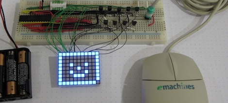
Many hacks are, of course, interesting in their own right. Hacks like this one, however, fulfill a much greater purpose by helping people overcome their disabilities. The PixBoard is “an illuminated board adapted for disabled people, especially for people with cerebral palsy, giving them access to games using shift technology.”

This device was developed for a girl that has cerebral palsy and can’t control her arms or legs effectively. In order to interact with the world more effectively to play board games and the like, this system was developed. The PixBoard scans an 8×8 matrix of LEDs allowing her to select the piece to be moved and where to move it. This is done using only simple buttons and the processor’s timer.

The system is controlled using an Arduino, so anyone is free to create their own games for this system depending on the situation. The following video is in Spanish, but shows this device in action around 1:20. Continue reading “The PixBoard”

Measuring RPM With Reflective Sensors

[Arao] wanted to measure the RPM of a spinning wheel using parts that he could scavenge from his junk box. A bit of thought led him to build a reflective sensor which can measure the spinning of a wheel (translated).

He got his hands on an infrared phototransistor which had been used as part of the remote control for some consumer electronics. Snooping around with his multimeter helped him establish the pin out of the device. By positioning an IR LED inside of a shroud, yet adjacent to the phototransistor, he can measure the intensity of the LED’s light as it is reflected off of nearby surfaces. The pulley seen above has a piece of electrical tape on it. When this passes by the LED, less of the infrared light is reflected and the drop in intensity is picked up by the phototransistor. [Arao] made the system rock-solid by rolling an LM358 op-amp into the circuit. He’s posted the schematic as well as some screen shots from an oscilloscope during testing.

Keeping Tabs On Your Pets’ Busy Lives

mouse_wheel_tracking

[Stephen’s] daughter has a pair of mice she keeps as pets, who happen to be quite active at night. After they kept her awake for an entire evening by running like mad in their treadmill, they were moved from her bedroom. Since they were so active in the treadmill, [Stephen] thought it would be cool to try measuring how much the mice actually ran each night.

To keep track of their activity, he built a simple circuit that records how many rotations the treadmill makes. He fitted it with a rare earth magnet, installing a reed switch on the outside of case that ticks off each spin of the wheel. Any time the wheel starts moving, his PIC begins counting the rotations, displaying them on a 7-segment LED display. To mitigate data loss in the event of a power outage, the PIC stores the current number of rotations in its EEPROM every 10 seconds or so.

The counter keeps track of the total number of rounds the mice have completed, which his daughter uses to manually calculate their running sessions. Since they started tracking the mice, they have run over 700,000 rounds, sometimes completing as many as 20,000 in an evening.

We think it’s a pretty cool project, especially since it makes it fun for his daughter to stay involved in her pets’ lives.

Reworking Ball Grid Array Circuit Board Components At Home

[Jack Gassett] is developing a new breakout board for an FPGA. The chip comes in a ball grid array (BGA) package which is notoriously difficult to solder reliably. Since he’s still in development, the test boards are being assembled in his basement. Of the first lot of four boards, only one is functional. So he’s setting out to rework the bad boards and we came along for the ride.

To reflow the surface mount components he picked up a cheap pancake griddle. The first thing [Jack] does is to heat up the board for about two minutes, then pluck off the FPGA and the FTDI chips using a vacuum tweezers. Next, the board gets a good cleaning with the help of a flux pen, some solder wick, and a regular soldering iron. Once clean, he hits the pads with solder paste from a syringe and begins the soldering process. BGA packages and the solder paste itself usually have manufacturer recommended time and temperature guidelines. [Jack] is following these profiles using the griddle’s temperature controller knob and the timer on an Android phone. In the video after the break you can see that he adjusts the timing based on gut reaction to what is going on with the solder. After cleaning up some solder bridges on the FTDI chip he tested it again and it works!

Continue reading “Reworking Ball Grid Array Circuit Board Components At Home”