Stamp breakout boards.

Stamp: Modular Breakout Boards For SMD Prototyping

[Kalesh Sasidharan] from Sciotronics wrote in to tell us about their project, Stamp: a modular set of template breakout boards designed to make prototyping with SMD components faster, easier, and more affordable. No breadboards, custom PCBs, or tangled jumper wires required. The project has blasted past its Kickstarter goal, and is on track to start shipping in September.

Stamp was created out of frustration with the traditional SMD prototyping workflow. Breadboards don’t support SMD parts directly, and using adapters quickly gets messy, especially when you need to iterate or modify a design. Ordering PCBs for every small revision just adds delay, and cost.

Stamp solves this by offering reusable template boards with commonly used SMD footprints. You place the main component on the front and the supporting components on the back. Many complete circuits, such as buck converters, sensor blocks, microcontrollers, and so on, can fit on a single 17.8 × 17.8 mm board.

Most Stamps feature custom castellated holes, designed for side-by-side or right-angle edge connections, enabling a modular, reconfigurable approach to circuit building. The plan is to make the designs fully open source, so that others can build or adapt them. Although many PCB manufacturers might not have the facilities to make the special castellated edges which are available on some Stamps.

Dave Jones from the EEVblog covered the Stamp on one of his recent Mailbag videos, which you can check out below. This isn’t the first time we’ve seen somebody promise to reinvent the breadboard, but we do appreciate the simplicity of this approach.

Continue reading “Stamp: Modular Breakout Boards For SMD Prototyping”

Two hands soldering components on a purpble PCB

Vintage Intel 8080 Runs On A Modern FPGA

If you’re into retro CPUs and don’t shy away from wiring old-school voltages, [Mark]’s latest Intel 8080 build will surely spark your enthusiasm. [Mark] has built a full system board for the venerable 8080A-1, pushing it to run at a slick 3.125 MHz. Remarkable is that he’s done so using a modern Microchip FPGA, without vendor lock-in or proprietary flashing tools. Every step is open source.

Getting this vintage setup to work required more than logical tinkering. Mark’s board supplies the ±5 V and +12 V rails the 8080 demands, plus clock and memory interfacing via the M2GL005-TQG144I FPGA. The design is lean: two-layer PCB, basic level-shifters, and a CM32 micro as USB-to-UART fallback. Not everything went smoothly: incorrect footprints, misrouted gate drivers, thermal runaway in the clock section; but he managed to tackle it.

What sets this project apart is the resurrection of a nearly 50-year-old CPU. It’s also, how thoroughly thought-out the modern bridge is—from bitstream loading via OpenOCD to clever debugging of crystal oscillator drift using a scope. [Mark]’s love of the architecture and attention to low-level detail makes this more than a show-off build.
Continue reading “Vintage Intel 8080 Runs On A Modern FPGA”

MiSTER Multisystem 2 on a wooden table

MiSTer For Mortals: Meet The Multisystem 2

If you’ve ever squinted at a DE10-Nano wondering where the fun part begins, you’re not alone. This review of the Mr. MultiSystem 2 by [Lee] lifts the veil on a surprisingly noob-friendly FPGA console that finally gets the MiSTer experience out of the tinker cave and into the living room. Developed by Heber, the same UK wizards behind the original MultiSystem, this follow-up console dares to blend flexibility with simplicity. No stack required.

It comes in two varieties, to be precise: with, or without analog ports. The analog edition features a 10-layer PCB with both HDMI and native RGB out, Meanwell PSU support, internal USB headers, and even space for an OLED or NFC reader. The latter can be used to “load” physical cards cartridge-style, which is just ridiculously charming. Even the 3D-printed enclosure is open-source and customisable – drill it, print it, or just colour it neon green. And for once, you don’t need to be a soldering wizard to use the thing. The FPGA is integrated in the mainboard. No RAM modules, no USB hub spaghetti. Just add some ROMs (legally, of course), and you’re off.

Despite its plug-and-play aspirations, there are some quirks – for example, the usual display inconsistencies and that eternal jungle of controller mappings. But hey, if that’s the price for versatility, it’s one you’d gladly pay. And if you ever get stuck, the MiSTer crowd will eat your question and spit out 12 solutions. It remains 100% compatible with the MiSTer software, but allows some additional future features, should developers wish to support them.

Want to learn more? This could be your entrance to the MiSTer scene without having to first earn a master’s in embedded systems. Will this become an alternative to the Taki Udon announced Playstation inspired all-in-one FPGA console? Check the video here and let us know in the comments. Continue reading “MiSTer For Mortals: Meet The Multisystem 2”

business card pcbs

Creative PCB Business Cards Are Sure To Make An Impression

Business cards are a simple way to share contact information, but a memorable design can make them stand out. [Jeremy Cook] has been experimenting with adding artistic finishes to PCBs, and has recently applied what he’s learned to make some unique business cards. His write-up consolidates some great resources to get you started in making your own PCB business cards, as well as PCB art in general

To make his cards stand out, he designed them to serve as functional tools beyond sharing contact information. He created two designs: one incorporates an LED and a coin cell battery holder, while the other includes drafting tools, such as a ruler, circle stencils, and a simplified protractor.

While the classic PCB solder mask is green, many board houses now offer alternative finishes and colors to enhance designs. He tested and compared the offerings from various manufacturers, highlighting the importance of researching fabrication options early, as different providers offer a variety of finishes. His creative approach shines in details like using through-hole pads as eyes in a robot illustration, making them stand out against a halftone dot pattern.

If you’re looking for more inspiration, be sure to check out the winners of our 2024 Business Card Challenge.

PCB Renewal Aims To Make Old Boards Useful Again

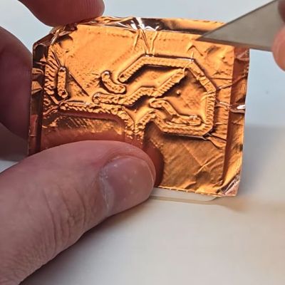
We’ve all made a few bad PCBs in our time. Sometimes they’re recoverable, and a few bodge wires will make ’em good. Sometimes they’re too far gone and we have to start again. But what if you could take an existing PCB, make a few mods, and turn it into the one you really want? That’s what “PCB Renewal” aims to do, as per the research paper from [Huaishu Peng] and the research group at the University of Maryland.

The plugin quantifies resource and time savings made by reusing an old board.

The concept is straightforward — PCB Renewal exists as a KiCad plugin that can analyze the differences between the PCB you have and the one you really want. Assuming they’re similar enough, it will generate toolpaths to modify the board with milling and epoxy deposition to create the traces you need out of the board you already have.

Obviously, there are limitations. You’ll never turn a PlayStation motherboard into something you could drop into an Xbox with a tool like this. Instead, it’s more about gradual modifications. Say you need to correct a couple of misplaced traces or missing grounds, or you want to swap one microcontroller for a similar unit on your existing board. Rather than making brand new PCBs, you could modify the ones you already have.

Of course, it’s worth noting that if you already have the hardware to do epoxy deposition and milling, you could probably just make new PCBs whenever you need them. However, PCB Renewal lets you save resources by not manufacturing new boards when you don’t have to.

We’ve seen work from [Huaishu Peng]’s research group before, too, in the form of an innovative “solderless PCB”.

Continue reading “PCB Renewal Aims To Make Old Boards Useful Again”

pinout leaf

Pinoutleaf: Simplifying Pinout References

We all appreciate clear easy-to-read reference materials. In that pursuit [Andreas] over at Splitbrain sent in his latest project, Pinoutleaf. This useful web app simplifies the creation of clean, professional board pinout reference images.

The app uses YAML or JSON configuration files to define the board, including photos for the front and back, the number and spacing of pins, and their names and attributes.For example, you can designate pin 3 as GPIO3 or A3, and the app will color-code these layers accordingly. The tool is designed to align with the standard 0.1″ pin spacing commonly used in breadboards. One clever feature is the automatic mirroring of labels for the rear photo, a lifesaver when you need to reverse-mount a board. Once your board is configured, Pinoutleaf generates an SVG image that you can download or print to slide over or under the pin headers, keeping your reference key easily accessible.

Visit the GitHub page to explore the tool’s features, including its Command-Line Interface for batch-generating pinouts for multiple boards. Creating clear documentation is challenging, so we love seeing projects like Pinoutleaf that make it easier to do it well.

Layout A PCB With Tscircuit

Most of us learned to design circuits with schematics. But if you get to a certain level of complexity, schematics are a pain. Modern designers — especially for digital circuits — prefer to use some kind of hardware description language.

There are a few options to do similar things with PCB layout, including tscircuit. There’s a walk-through for using it to create an LED matrix and you can even try it out online, if you like. If you’re more of a visual learner, there’s also an introductory video you can watch below.

Continue reading “Layout A PCB With Tscircuit”