Flexible PCBs: Not Only For The Few

Flexible printed circuit boards are a fascinating technique for making electronics venture beyond the two-dimensional, but surprisingly they’re not something many of us have worked with. [Jessica Stanley] gave a talk at the recent Electromagnetic Field event in the UK, exploring the different ways to make your electronics bend.

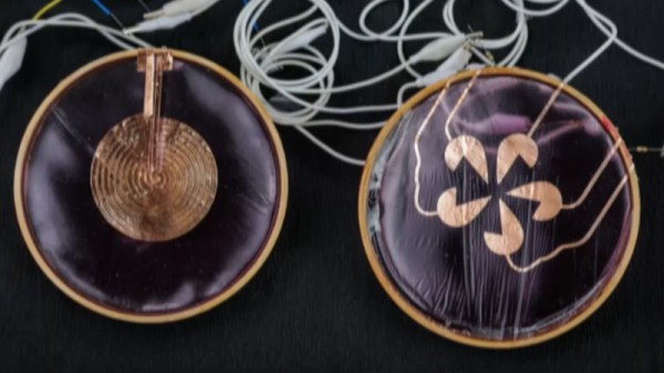
She starts with an overview of flexible electronics, detailing the techniques used with conventional polyimide substrates and etched copper.  We’re particularly enamoured of a stretchable PCB made by coiling a flexible circuit round a piece of elastic. Since she’s looking for techniques accessible to everyone that don’t either cost a fortune or require dangerous chemicals we look at conductive paint and electrolysis, before arriving at using a vinyl cutter to create adhesive traces.

We’ve no doubt all noticed that flexible PCBs can be ordered from the usual fabrication houses at a price, but the value in this talk lies in reminding the viewer that this is not the only path. She demonstrates well that simple flexible PCBs can be within the reach of almost anyone, which is perhaps the encouragement needed for people to try this medium. The full talk is below the break.

Continue reading “Flexible PCBs: Not Only For The Few”

A person's hand wearing a black glove is shown in the right part of the image, making a series of gestures. A representation of a hand mimics those motions on a laptop screen.

Weaving Circuits From Electronic Threads

Though threading is a old concept in computer science, and fabric computing has been a term for about thirty years, the terminology has so far been more metaphorical than strictly descriptive. [Cedric Honnet]’s FiberCircuits project, on the other hand, takes a much more literal to weaving technology “into the fabric of everyday life,” to borrow the phrase from [Mark Weiser]’s vision of computing which inspired this project. [Cedric] realized that some microcontrollers are small enough to fit into fibers no thicker than a strand of yarn, and used them to design these open-source threads of electronics (open-access paper).

The physical design of the FiberCircuits was inspired by LED filaments: a flexible PCB wrapped in a protective silicone coating, optionally with a protective layer of braiding surrounding it. There are two kinds of fiber: the main fiber and display fibers. The main fiber (1.5 mm wide) holds an STM32 microcontroller, a magnetometer, an accelerometer, and a GPIO pin to interface with external sensors or other fibers. The display fibers are thinner at only one millimeter, and hold an array of addressable LEDs. In testing, the fibers could withstand six Newtons of force and be bent ten thousand times without damage; fibers protected by braiding even survived 40 cycles in a washing machine without any damage. [Cedrik] notes that finding a PCB manufacturer that will make the thin traces required for this circuit board is a bit difficult, but if you’d like to give it a try, the design files are on GitHub.

[Cedrik] also showed off a few interesting applications of the thread, including a cyclist’s beanie with automatic integrated turn signals, a woven fitness tracker, and a glove that senses the wearer’s hand position; we’re sure the community can find many more uses. The fibers could be embroidered onto clothing, or embedded into woven or knitted fabrics. On the programming side, [Cedrik] ported support for this specific STM32 core to the Arduino ecosystem, and it’s now maintained upstream by the STM32duino project, which should make integration (metaphorically) seamless.

One area for future improvement is in power, which is currently supplied by small lithium batteries; it would be interesting to see an integration of this with power over skin. This might be a bit more robust, but it isn’t first knitted piece of electronics we’ve seen. Of course, rather than making wearables more unobtrusive, you can go in the opposite direction. Continue reading “Weaving Circuits From Electronic Threads”

Transparent PCBs Trigger 90s Nostalgia

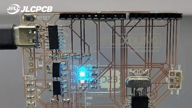
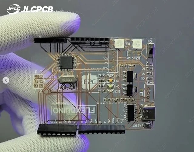
What color do you like your microcontroller boards? Blue? Red? Maybe white or black? Sadly, all of those are about to look old hat. Why? Well, as shared by [JLCPCB], this transparent Arduino looks amazing.

The board house produced this marvel using its transparent flexible printed circuit (FPC) material. Basically, the stuff they use for ribbon cables and flex PCBs, just made slightly differently to be see-through instead of vaguely brown.

The circuit in question is a Flexduino, an Arduino clone specifically designed to work on flexible substrates. It looks particularly good on this transparent material, with the LEDs glowing and the white silkscreen for contrast. If you like what you see, you can order your own circuits using this material directly from JLCPCB’s regular old order form.

Most of all, this project reminds us of the 1990s. Back then, you could get all kinds of games consoles and other electronics with transparent housings. There was the beloved PlayStation Crystal, while Nintendo did something similar with the N64 while adding a whole line of tinted color and charcoal versions too. Somehow seeing a bit of the inside of things is just cool. Even if, in some cases, it’s just to avoid smuggling in prisons.

It took decades before you could get custom PCBs quickly and easily. Now, board houses are competing for the enthusiast (consumer?) market, and competition is spurring development of crazy stuff like transparent and even glow in the dark PCBs. What next? We’re thinking edible, ROHS and WEEE be damned. Drop your thoughts in the comments.

Thanks to [George Graves] for the tip!

Magnets Turn Flexible PCB Into Electric Grasshopper

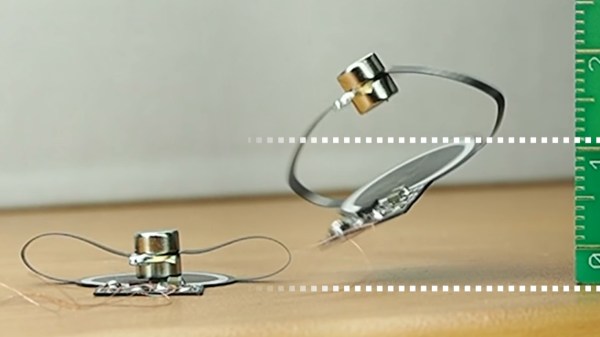
Just because something doesn’t seem to have an apparent purpose, that doesn’t mean we shouldn’t try making it anyway. As flexible PCBs become cheaper and easier to order from low-scale fab houses, we’re seeing hobbyists experiment with new uses for them such as [Carl Bugeja]’s jumping circuit.

The circuit is based a coil printed on the flexible PCB itself acting as an electromagnet, but unlike other designs which use the same trick, in this one the coil is made to be the static side of an actuator. Attached to the circuit with folding arms is a stack of two permanent magnets, which work as the moving part. Since the magnets make up most of the mass of the circuit, as they’re pushed down and sprung back up, it causes the whole thing to leap around just under one centimeter off the table like a little electric grasshopper.

This is far from [Carl]’s first appearance here on Hackaday, and he’s been clearly busy exploring new uses for flexible PCBs with their properties as electromagnets, from making POV displays with them to small robots that move around through vibration. We’re excited to see what else he can come up with, and you can see this one in action after the break.

Continue reading “Magnets Turn Flexible PCB Into Electric Grasshopper”

Origami Butterfly: A Flex PCB Adventure Unfolds

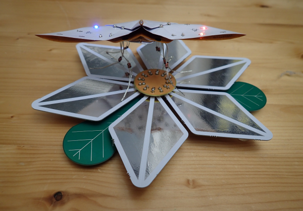
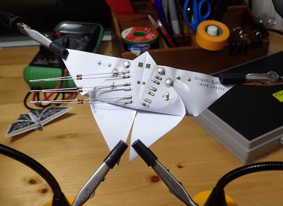
Flexible circuits have been around longer than you might expect, although they only recently rounded the bend and bounced into the hobbyist’s toolbox. When Boldport fanatic [Laura Lindzey] found out about them, her immediate dream project was to make an origami butterfly that does something cool, though she wasn’t sure what.

The idea she landed on is this: when the butterfly alights on a power-providing flower, it draws electrical nectar through its diode legs and lights up the LEDs on its wings. As long as one leg touches a ground petal and another touches a VIN petal, there will be light.

Though the idea may be simple, it’s the execution that’s mind-bending. After meticulous planning and a lot of paper prototyping, she sent off the gerbers and got version one back. The circuit worked, but assembly was tedious — not what you want when you’re trying to stay friendly with the other people in your PCB exchange club.

We imagine that hard creases are probably not what the flexible PCB purveyors have in mind, but this origami butterfly is an awesome exercise in what can be done with flexible PCBs. Not only that, it’s a great insight into some design rules where almost none exist, learned through firsthand experience. Every technology can benefit from trailblazers like [Laura].

If you want to do some flexible prototyping at home, just print your own pliable PCBs.

Arduboy Goes Thin And Flexible For Portable Gaming

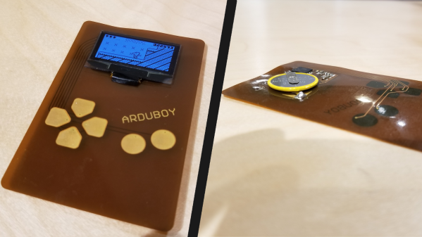
We all have a gaming system in our pocket or purse and some of us are probably reading on it right now. That pocket space is valuable so we have to budget what we keep in there and adding another gaming system is not in the cards, if it takes up too much space. [Kevin Bates] budgeted the smallest bit of pocket real estate for his full-size Arduboy clone, Arduflexboy. It is thin and conforms to his pocket because the custom PCB uses a flexible substrate and he has done away with the traditional tactile buttons.

Won’t a flexible system be hard to play? Yes. [Kevin] said it himself, and while we don’t disagree, a functional Arduboy on a flexible circuit makes up for practicality by being a neat manufacturing demonstration. This falls under the because-I-can category but the thought that went into it is also evident. All the components mount opposite the screen so it looks clean from the front and the components will not be subject to as much flexing and the inputs are in the same place as a traditional Arduboy.

cost = low, practicality = extremely low, customer service problems = high

     ~[Kevin Bates]

These flexible circuit boards use a polyimide substrate, the same stuff as Kapton tape, and ordering boards is getting cheaper so we can expect to see more of them popping up. Did we mention that we currently have a contest for flexible circuits? We have prizes that will make you sing, just for publishing your flex PCB concept.

Continue reading “Arduboy Goes Thin And Flexible For Portable Gaming”

Flex PCBs Make Force-Mapping Pressure Sensor For Amputee

What prosthetic limbs can do these days is nothing short of miraculous, and can change the life of an amputee in so many ways. But no matter what advanced sensors and actuators are added to the prosthetic, it has to interface with the wearer’s body, and that can lead to problems.

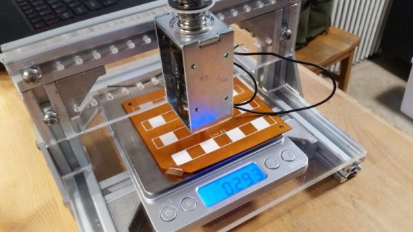
Measuring and mapping the pressure on the residual limb is the business of this flexible force-sensing matrix. The idea for a two-dimensional force map came from one of [chris.coulson]’s classmates, an amputee who developed a single-channel pressure sensor to help him solve a painful fitting problem. [chris.coulson] was reminded of a piezoresistive yoga mat build from [Marco Reps], which we featured a while back, and figured a scaled-down version might be just the thing to map pressure points across the prosthetic interface. Rather than the expensive and tediously-applied web of copper tape [Marco] used, [chris] chose flexible PCBs to sandwich the Velostat piezoresistive material. An interface board multiplexes the 16 elements of the sensor array to a PIC which gathers and records testing data. [chris] even built a test stand with a solenoid to apply pressure to the sensor and test its frequency response to determine what sorts of measurements are possible.

We think the project is a great application for flex PCBs, and a perfect entry into our Flexible PCB Contest. You should enter too. Even though [chris] has a prototype, you don’t need one to enter: just an idea would do. Do something up on Fritzing, make a full EAGLE schematic, or just jot a block diagram down on a napkin. We want to see your ideas, and if it’s good enough you can win a flex PCB to get you started. What are you waiting for?