[Texane] is developing a system to monitor his garage door from his apartment. Being seven floors apart, running wires between the door and apartment wasn’t an option, so he turned to a wireless solution. Testing this wireless hardware in an apartment is no problem, but testing it in situ is a little more difficult. For that, he turned to software defined radio with an RTLSDR dongle.
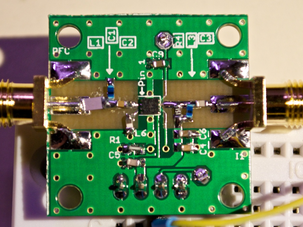
The hardware for this project is based around a TI Stellaris board and a PTR8000 radio module. All the code for this project was written from scratch (Github here), making it questionable if the code worked on the first try. To test his code, [Texane] picked up one of those USB TV tuner dongles based around the RTL2832U chipset. This allowed him to monitor the frequencies around 433MHz for the packets his hardware should be sending.
After that, the only thing left to do was to write a frame decoder for his radio module. Luckily, the datasheet for the module made this task easy.
[Texane] has a frame decoder for the NRF905 radio module available in his Git. It’s not quite ready for serious applications, but for testing a simple radio link it’s more than enough.
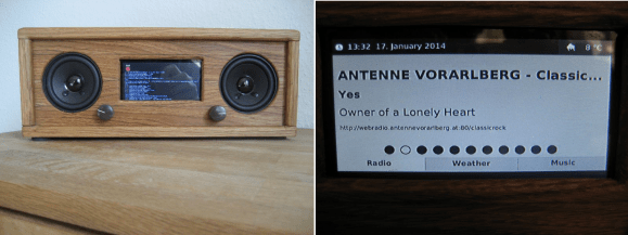 Avid Hackaday reader [Matthias] told us he takes a lot of inspiration from our site. That’s quite a compliment, because his work is both inspiring and beautiful. [Matthias] wanted to build a UI using JavaFX, so he made