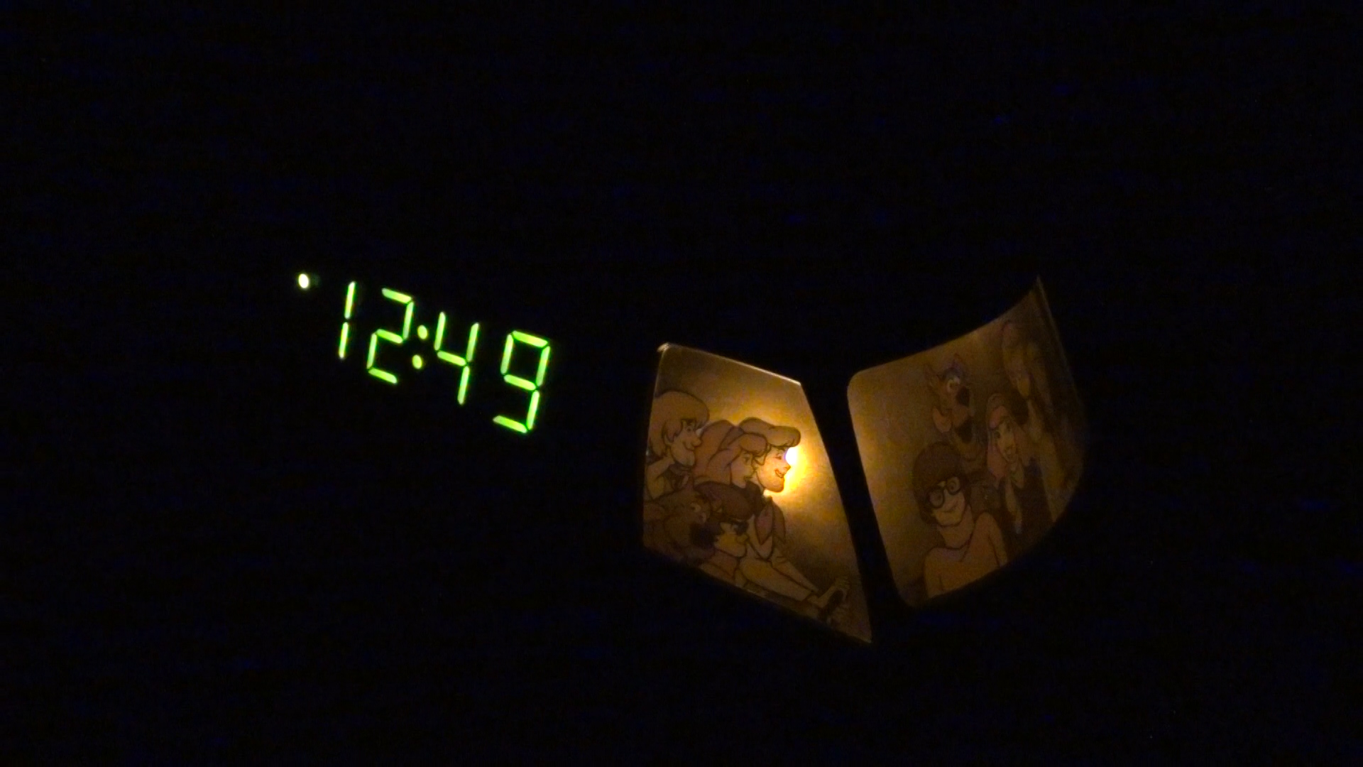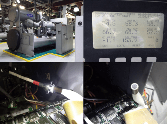
[N8Mcnasty] is a HVAC tech who works on some big machines. One of his charges is a Carrier 19EX Chiller, rated at 1350 tons of cooling. 1 ton of cooling = 12,000 BTU. This particular chiller contained an odd LCD screen. It used a fiber optic bundle and a halogen light for backlight illumination. The system worked fine for over a decade. Now though, the halogen bulb has begun melting the glue on the fiber bundle, causing a dim display. The display in question shows some very important operating parameters, such as oil temperature, current draw, and process temperatures. Since they couldn’t easily see the display, the machine’s operators weren’t running the machine, placing stress on the other chillers in the building’s physical plant. [N8Mcnasty] tried repairing the bundle, however the glue kept melting.
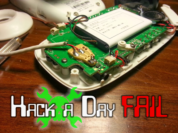
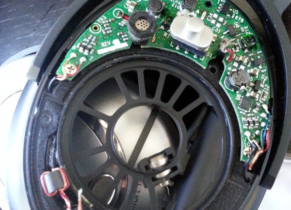
A replacement display was no longer available, meaning that the entire chiller control system would have to be upgraded to a newer system. The new control system uses different sensors than the old one. This is where things start getting expensive. Replacing the sensors would also require draining the 15-20 gallons of oil, 4500 lbs of R134a refrigerant, and bringing the whole system down for almost two weeks, a $20,000 job. Rather than go this route, [N8Mcnasty] found an alternative. LED’s have come a long way since 1996, when the chiller was built. He simply replaced the halogen bulb with an LED and appropriate resistor. [N8Mcnasty] was even able to reuse the halogen bulb bracket. A bit of heat shrink tube later, and the fix looks like it was a factory option. He’s documented his fix here on reddit.