[Brandon Lai] is hoping to build a humanoid robot. To that end, he’s going to need some actuators, and decided to design his own. His second pass at this turned out pretty well, with a few snags found along the way.
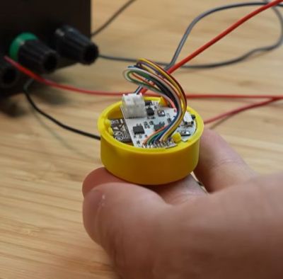
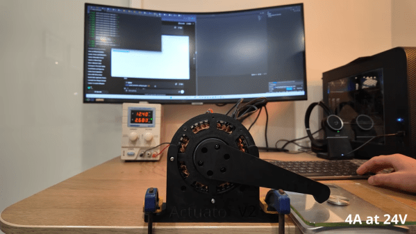
Target specs were a actuator that could run at 40 to 60 rpm while delivering 20 Nm of torque for up to an hour continuously. The design was inspired by an MIT research paper, with [Brandon] making a few mods to suit his use case. Where the MIT design uses an inbuilt planetary gearbox, this build substitutes a cycloidal gearbox with a hope it will provide better torque capacity with less backlash. The design is based around a hand-wound stator made with an off-the-shelf core, while using custom CNC parts and 3D printed components for the motor housing itself.
Testing revealed some limitations. Running off a benchtop power supply with limited current, the motor was only able to achieve 7 Nm of torque, though a better PSU would probably improve this. [Brandon] also noted excessive backlash in the cycloidal gearbox, due to poor tolerances, and the $400 construction cost came in well over budget. Still, [Brandon] hopes to tackle many of these problems in a future revision. CAD files are available online if you’d like to dig deeper into the design.
We’ve featured plenty of great actuator builds over the years. Video after the break.
Continue reading “Building And Testing A DIY Robot Actuator”

 One of the joys you get to experience whether as a proud parent or pet owner is that a lot of things get left around haphazardly. You could of course pick every piece of discarded clothing, half-destroyed toy and detritus yourself, but as a parent of three children himself [Nathaniel Nifong] opted to use his engineering background to potentially over engineer a wires-suspended robotic claw