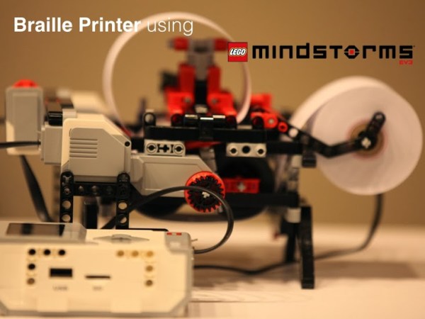
Accessibility devices tend to be prohibitively expensive, and it’s always nice to see a hacker apply their skills to making these devices more affordable. BRAIGO is a low cost braille printer by [Shubham Banerjee]. He built the printer using parts from the LEGO Mindstorms EV3 kit, with a few additions. This LEGO kit retails for $349, and a standard braille printer costs over $2000.
The BRAIGO print head uses weights and a pin to punch holes in standard calculator paper rolls. LEGO motors are used to feed the paper and align the head for accurate printing. It takes about 5 to 7 seconds to print each letter, which are entered on the Mindstorms controller.
While this is a great prototype, [Shubham] intends to continue development with the goal of creating an affordable braille printer. He’s a bit swamped with media requests right now, but is working on releasing BRAIGO as an open source project so others can contribute. It’s an impressive project, especially for a 12 year old student. After the break, watch the BRAIGO do some printing.
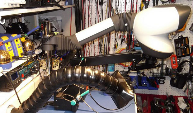
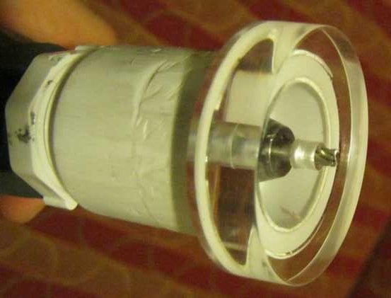
 Like a lot of us, [Andrea] has a habit of disassembling everything he runs into. He recently came across a fairly substantial motor he’d salvaged and envisioned