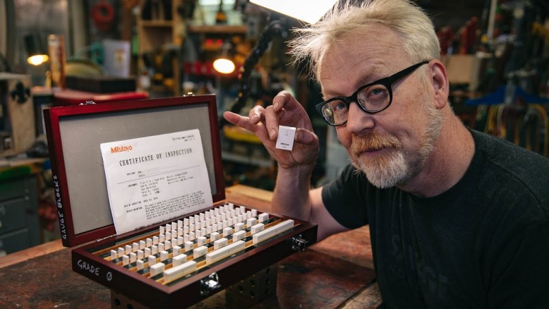
It’s commonly said that the great thing about standards is that there are so many of them. Of course, that’s talking about competing standards. But there’s another kind of standard that you want a lot of: Measurements. Without standard measurements, the Industrial Revolution wouldn’t have been facilitated to the extent it was. The illustrious [Adam Savage] takes a deep dive into the art of measurement in the video below the break, and if you have 45 minutes to spare, you will not be disappointed.
We don’t want to give away any big spoilers, but [Adam] starts out with things we can all relate to if we’ve done any kind of measuring for accuracy: measuring between the given lines on a standard tape measure. From there he goes into calipers and other tools for measurement.
Then, out come the Big Guns. The ceramic blocks so flat that… well you’ll just have to watch it. But the discussion goes deep into nanometers, microns, and jeweled movements.
Whether you’re a machinist or a garage hacker with nothing more than a stick welder and an angle grinder at your disposal, or anywhere in between in any segment of being a maker, this video is for you. [Adam]’s enthusiasm is off the charts in this diatribe, and we have to admit- it’s contagious! We’ve never been so excited about measuring things.
Of course, if you need to measurement tool, you can just build a measurement tool. It’s all subjective, after all.
Continue reading “A Savage Discussion Of Measurement And Accuracy”

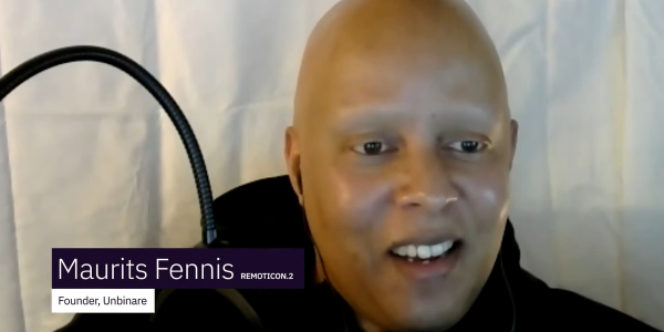
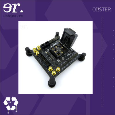 Unbinare’s tools are designed to work in harmony with each other, a requirement for any productive reverse-engineering effort. OI!STER is a general-purpose salvaged MCU research board, with sockets to adapt to different TQFP chip sizes. This board is Maurits’s experience in reverse-engineering condensed into a universal tool, including a myriad of connectors for different programming/debugging interfaces. We don’t know the board’s full scope, but the pictures show an STM32 chip inside the TQFP socket, abundant everywhere except your online retailer of choice. Apart from all the ways to break out the pins, OI!STER has sockets for power and clock glitching, letting you target these two omnipresent Achilles’ heels with a tool like ChipWhisperer.
![USB to Dupont adapter by [PROSCH]](https://hackaday.com/wp-content/uploads/2022/01/2022-01-01-USB-to-DuPont-adapter-feat.jpg?w=600&h=450)