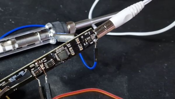
With soldering irons being so incredibly useful, and coming on the heels of the success of a range of portable, all-in-one soldering irons from the likes of Waveshare and Pine64, it’s little wonder that you can get such devices for as little as 10 – 15 Euro from websites like AliExpress. Making for both a great impulse buy and reverse-engineering target, [Aaron Christophel] got his mittens on one and set to work on figuring out its secrets.
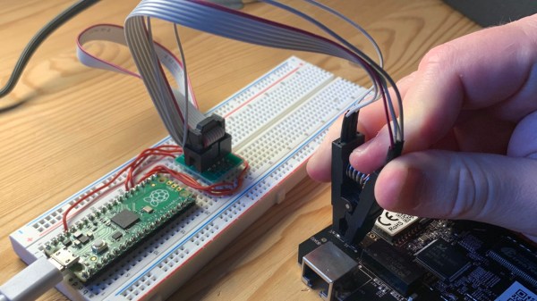
The results are covered in a brief video, as well as a Twitter thread, where this T12 soldering iron’s guts are splayed around and reprogrammed in all their glory. Despite the MCU on the PCB having had its markings removed, some prodding and poking around revealed it to be an STC8H3K62S2, an 8051-based MCU running at a blistering 11 MHz. As a supported PlaformIO target, reprogramming the MCU wasn’t too complicated after wiring up a USB-TTL serial adapter.
Completing this initial foray into these cheap T12 soldering irons is the GitHub repository, which contains the pin-outs, wiring diagrams and further information. Although [Aaron] indicates that he’ll likely not pursuing further development, the mixed responses by people to the overall quality of the firmware on the as-purchased T12 may inspire others to give it a shake.
Continue reading “Hacking A €15 8051-Based Portable Soldering Iron With Custom Firmware”
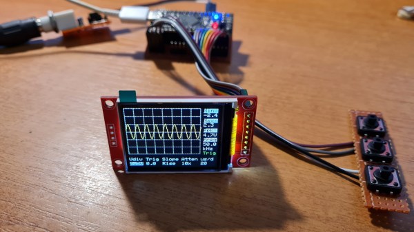
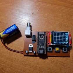 It’s hard to overshadow just how easy this scope is to build, use, and hack on. You really don’t need much in the way of parts, a protoboard will do, though you can also etch or order