With the radio control hobby arguably larger now than it ever has been in the past, there’s a growing demand for high-fidelity PC simulators. Whether you want to be able to “fly” when it’s raining out or you just want to practice your moves before taking that expensive quadcopter up for real, a good simulator on your computer is the next best thing. But the simulator won’t do you much good if it doesn’t feel the same; you really need to hook your normal RC transmitter up to the computer for the best experience.
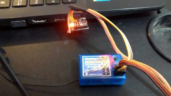
 [Patricio] writes in to share with us his simple hack for interfacing his RC hardware to his computer over USB. Rather than plugging the transmitter into the computer, his approach allows the receiver to mimic a USB joystick. Not only is this more convenient since you can use the simulator without wires, but it will make sure that the minutiae of your radio hardware (such as response lag) is represented in the simulation.
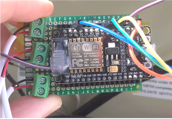
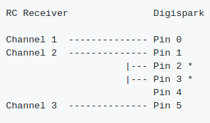
The setup is actually very simple. [Patricio] used the ATtiny85 based Digispark development board because it’s what he had on hand, but the principle would be the same on other microcontrollers. Simply connect the various channels from the RC receiver to the digital input pins. RC receivers are 5 VDC and draw very little current, so it’s even possible to power the whole arrangement from the USB port.
On the software side, the Arduino sketch does about what you expect. It loops through listening for PWM signals on the input pins, and maps that to USB joystick position information. The current code only supports three channels for a simple airplane setup (X and Y for joystick, plus throttle), but it should be easy enough to follow along and add more channels if you needed them for more complex aircraft.
For more information on the intricacies of RC transmitter and receiver interaction, check out this fascinating research on receiver latency.

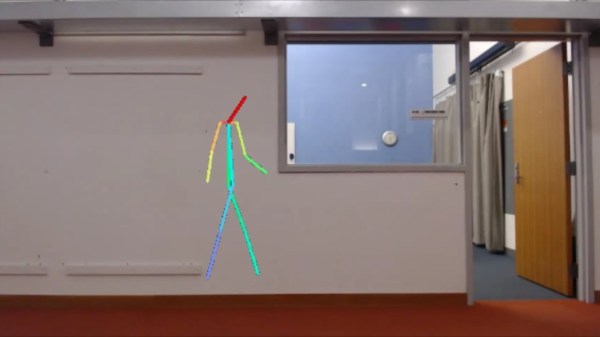
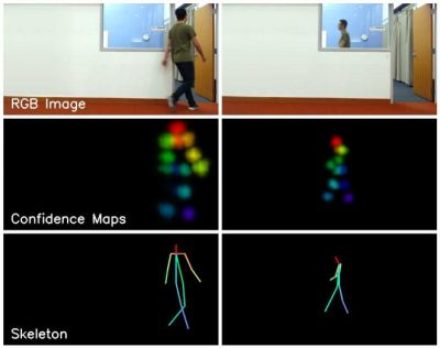 This is the work of a group at the MIT Computer Science and Artificial Intelligence Laboratory (CSAIL). The seeing-through-the-wall part is done using an RF transmitter and receiving antennas, which isn’t very new. Our own [Gregory L. Charvat]