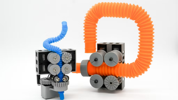
Need a hinge in your 3D printed design and would prefer not to re-invent the wheel? You may find [Alex Krush]’s glue-in filament hinge useful.
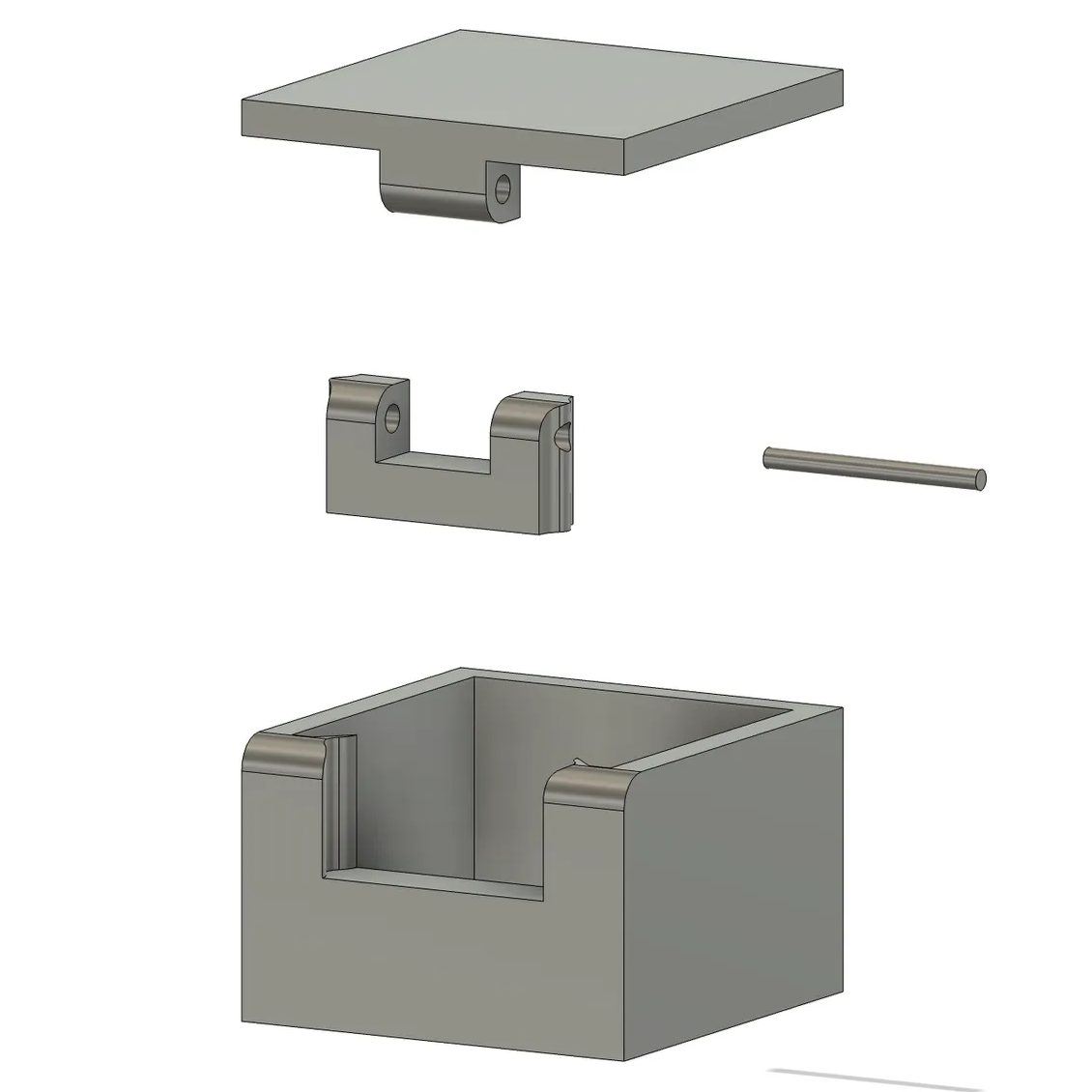
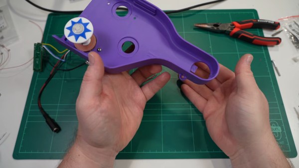
This design prints half the hinge as a separate piece — the u-shaped one in the picture to the side — that must be glued into the target object after printing. It’s a bit of extra work, but doing it this way has a couple advantages.
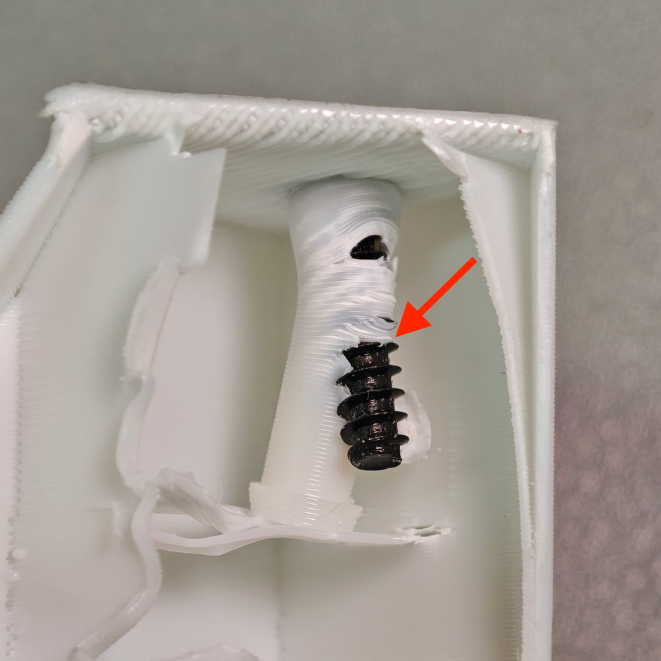
One is that printing some of the hinge elements separately means one no longer needs to choose between a print orientation that best suits the object, and a print orientation that works best for the hinge. Also, the length of 1.75 mm filament used as a hinge pin is held captive after assembly so there’s no need to glue the hinge pin itself.
[Alex] helpfully provides the parts in STEP format, which makes CAD tweaks and adjustments easy. While incorporating the design should be doable even if one is just using .stl or .3mf files because boolean subtraction and merging is all that’s needed, having the model in STEP format is so much better.
Should you need some pointers on incorporating either into FreeCAD, we have you covered.