The age of steam is long gone, but there are few railfans who don’t have a soft spot for the old rolling kettles. So you’d best believe when [AeroKoi] talks about 3D printed train whistles, that’s steam whistles. Generally speaking, Diesels have horns.
You would not expect printed plastic to hold up to live steam– but that’s why [AeroKoi] uses compressed air. Besides, it’s a lot easier to both justify and maintain an air compressor than a boiler in the shop. At least some hobbyists say it doesn’t make a huge difference with brass whistles, so it should be good enough for plastic. What’s interesting is that even with 120 PSI blasting through them, these multi-part prints held together and sounded amazing.
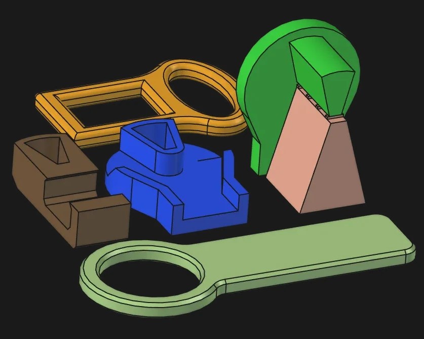
[AeroKoi] does demonstrate there was a learning curve to climb before he had a good whistle design, and shows you what features worked best. He shared two successes on Thingiverse: A 6-Chime whistle from the Sante Fe Railroad, and a Northern Pacific 5-chime whistle, both 4″ in diameter and printed in vertically sectioned parts. The Northern Pacific is not to be confused with the totally different Union Pacific Railroad, whose famous “Big Boy” also had a whistle feature in the video — though evidently he’s not as happy with it, since he did not share the design.
Those are all North American designs, but there’s no reason this technique wouldn’t work to replicate a more European sound; one of his early experiments was kind of going in that direction already. Of course if you want a perfect replica, the old ways are the best ways: cast brass and live steam. We’ve had a few articles about train whistles in the past, one of which was a doorbell.
Continue reading “3D Printed Train Whistles Sound Out At Full Scale”