[Carlos] needed an ADC with a 50 nanosecond sample period for his laser lab, that’s 20Msps! (20 million samples a second). While in recent years, commodity ADCs reaching into the low GSPS have become available, integrated acquisition systems are still somewhat expensive. So [Carlos] decided to do what every good hacker does, and built his own solution. His project post pretty much just links to a whitepaper he wrote (PDF) so we’ll try and boil it down for you:
In order to simplify development [Carlos] borrowed a technique commonly used in the first era of digital oscilloscopes, Equivalent Sampling Time.
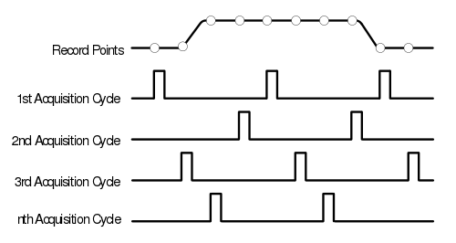
The figure to the right is from the TDS460 manual. While it may seem counter intuitive to those only familiar with modern scopes, the TDS460 achieved a 400MHz bandwidth using a 100MSPS ADC. In order to achieve this the scope acquires a single trace in multiple cycles, each time offsetting the acquisitions as shown and combining the result.
In this way, early digital scope developers could sidestep the limitations of the available ADCs to achieve a higher effective bandwidth. However there is of course one catch: the technique only works for periodic signals.
This was fine for [Carlos] who implemented a technique on a Cypress PSoC 4, which provides analog FPGA-like functionality. By offsetting the ADC trigger he has able to achieve an EST of 48MHz using a ADC sampling at 1MHz. If you want a little help getting into PSOC 4 yourself, check out the guide that [Bil Herd] made.
Neat hack [Carlos] and we hope to hear more about your laser lab in the future.