Need A Nano-Ammeter? You Already Have One!

[Dannyelectronics] sometimes needs to measure tiny currents. Really tiny, like leakage currents through a capacitor. He’s built a few setups to make the measurements, but he also knew he’d sometimes want to take readings when he didn’t have his custom gear available. So he decided to see what he could do with an ordinary digital meter.

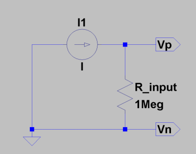
dmm-nano-ammeterAs you might expect, a common digital meter’s current scales aren’t usually up to measuring nano- or pico-amps. [Danny’s] approach was not to use the ammeter scale. Instead, he measures the voltage developed across the input impedance of the meter (which is usually very high, like one megaohm). If you know the input characteristics of the meter (or can calibrate against a known source), you can convert the voltage to a current.
For example, on a Fluke 115 meter, [Danny] found that he could read up to 60nA with a resolution of 0.01nA. A Viktor 81D could resolve down to 2.5pA–a minuscule current indeed.

We’ve looked at the difficulties involved in reading small currents before. If tiny currents aren’t your thing, maybe you’d like to try charging an iPhone with 3 KA, instead.

Current Meter Shows Current Time

This isn’t the first of its type, but [Daniel]’s MSP430 based Analog Gauge Clock certainly ticks off the “hack” quotient. He admits an earlier Voltmeter Clock we featured a while back inspired him to build his version.

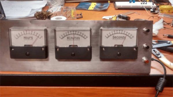
[Daniel] was taking an Embedded systems class, and needed to build an MSP430G2553 microcontroller based final project. Which is why he decided to implement the real time clock using the micro-controller itself, instead of using an external RTC module. This also simplified the hardware used – the microcontroller, a crystal, three analog ammeters, and a few passives were all that he needed. Other than the Ammeters, everything else came from his parts bin. Fresh face plates were put on the ammeters, and the circuit was assembled on a piece of strip board. A piece of bent steel plate served as the housing.

The interesting part is the software. He wrote all of it in bare C, without resorting to using the Energia IDE. He walks through all of the important parts of his code on his blog post. Setting load capacitance for the timing crystal was important, so he experimented with an oscilloscope to see which value worked best. And TI’s Application Note on MSP430 32-kHz Crystal Oscillators (PDF) proved to be a useful resource. Three PWM output’s run the three ammeters which indicate hours, minutes and seconds. Push-button switches let him set the clock. See a short demo of the clock in the video below.

Continue reading “Current Meter Shows Current Time”

Retrotechtacular: Weston Electrical Instruments

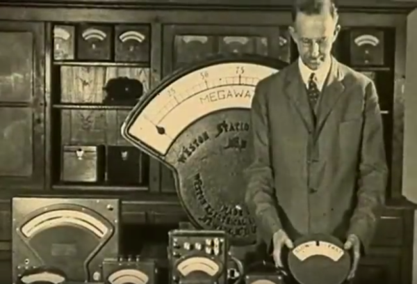
A ‘meter is one of the most important tools on any electronics bench. After you’ve exhausted your five senses trying to figure out what’s happening in a circuit, firing up the old ‘meter is usually the next step. Meters are largely digital nowadays, but their analog ancestors are still widely available. We have a chemist and inventor named [Edward Weston] to thank for the portability and ubiquity of DC measuring equipment.

After immigrating to the United States from England with the degree in medicine his parents wanted him to earn, [Edward Weston] asserted that he was more interested in chemistry. His career began in electroplating, where he soon realized that he needed a reliable, constant current source to do quality plating. This intense interest in power generation led him to develop a saturated cadmium cell, which is known as the Weston cell. Its chemistry produces a voltage stable enough to be used for meter calibration. The Weston cell is also good for making EMF determinations.

Within a few years, he co-founded the Weston Electrical Instrument Corporation. The company produced several types of meters along with transformers and transducers known for their portability and accuracy. In 1920, [Weston & Co.] created this 1920 educational film in cooperation with the United States Navy as part of a series on the principles of electricity.

The viewer is invited to consider the importance of measurement to civilization, most notably those fundamental measurements of length, mass, and time. [Weston] positions his electrical measuring instruments at this level, touting them as the international favorite. We get the full tour of a Weston meter, from the magnet treated for permanence to the specially designed pole pieces that correctly distribute lines of magnetic force. What education film about electromagnetism would be complete without an iron filings demonstration? This one definitely delivers.

Continue reading “Retrotechtacular: Weston Electrical Instruments”

Fail Of The Week : Measuring DC Current Has To Be Easy, Right?

[DainBramage] needed a DC ammeter to check how long his amateur radio station would be able to stay powered on battery backup power. The one’s he already had on hand were a Clamp Meter, which could only measure AC, and another one that measured just a few milliamps. Since he didn’t have one which could measure up to 25A, he decided to build his own DIY DC Ammeter with parts scavenged from his parts bin. Measuring DC current is not too difficult. Pass the current to be measured through a precision resistor, and measure the voltage drop across it using a sensitive voltmeter.

I = V/R

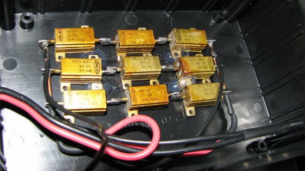
So far, so good. If it’s late at night and you’ve had a lot of coffee, busy building your DC ammeter, things could head south soon. [DainBramage]’s first step was to build a suitable Shunt. He had a lot of old, 1Ω, 10W resistors lying around. He made a series-parallel combination using nine of them to create a hefty 1Ω, 90W shunt (well, 0.999999999 Ohms if you want to be picky). This gave him a nice 1 Volt per Amp ratio, making it easy to do his measurements.

Next step was to hook up the shunt to a suitable voltmeter. Luckily, he had a Micronta voltmeter lying around, ripped out from a Radio Shack product. Since he didn’t have the voltmeter data, he hooked up a 10k resistor across the meter inputs, and slowly increased the voltage applied to the meter. At 260mV, the needle touched full-scale and the voltage across the inputs of the voltmeter was 33mV. [DainBramage] then describes the math he used to calculate the resistors he would need to have a 10A and a 25A measurement range. He misses his chance to catch the fail. His project log then describes some of the boring details of putting all this together inside a case and wrapping it all up.

A while later, his updates crop up. First thing he probably realized was that he needed more accurate readings, so he added connectors to allow attaching a more accurate voltmeter instead of the analog Micronta. At this point, he still didn’t catch the fail although it’s staring him straight in the face.

His head scratching moment comes when he tries to connect his home made ammeter in series with the 12V DC power supply to his amateur radio station. Every time he tries to transmit (which is when the Radio is drawing some current), the Radio shuts off.  If you still haven’t spotted the fail, try figuring out how much voltage gets dropped across the 1Ω shunt resistor when the current is 1A and when it is 5A or more.