Mechanical CPU Clock Is Just As Confusing As Its Namesake

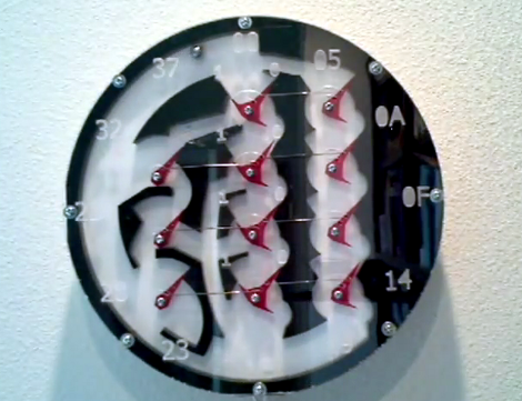
[Lior Elazary] designed and built this clock to simulate the function of a CPU. The problem is that if you don’t already have a good grasp of how a CPU works we think this clock will be hopelessly confusing. But lucky for us, we get it, and we love it!

Hour data is shown as a binary number on Register A. This is the center column of red parts and is organized with the MSB on the bottom, the LSB on the top, and left-pointing bits function as digital 1. The clock lacks the complexity necessary for displaying any other time data. But that’s okay, because the sound made by the ball-bearing dropping every minute might drive you a bit loony anyway. [Lior] doesn’t talk about the mechanism that transports that ball bearing, but you can see from the video after the break that a magnet on a circular path picks it up and transports it to the top of the clock where gravity is used to feed the registers. There are two tracks which allow the ball to bypass the A register and enter the B register to the right. This works in conjunction with register C (on the left) to reset the hours when the count is greater than 11.

If you need a kickstart on how these mechanical adders are put together, check out this wooden adder project.

Continue reading “Mechanical CPU Clock Is Just As Confusing As Its Namesake”

Intermediate Concepts: Building Discrete Transistor Gates

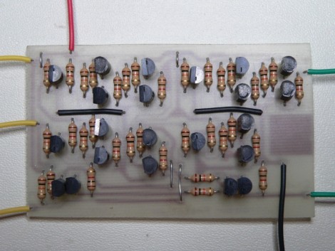
[Simon Inns] has put together a lesson in digital logic which shows you how to build your own gates using transistors. The image above is a full-adder that he fabricated, then combined with other full adders to create a 4-bit computer.

Don’t know what a full adder is? That’s exactly what his article is for, and will teach you about binary math and how it is calculated with hardware. There’s probably at least a week’s worth of studying in that one page which has been further distilled into the five-minute video after the break. Although building this hardware yourself is a wonderful way to learn, there’s a lot of room for error. You might consider building these circuits in a simulator program like Atanua, where you can work with logic gate symbols, using virtual buttons and LEDs as the outputs. Once you know what you’re doing with the simulator you’ll have much more confidence to start a physical build like the one [Simon] concocted.

Finding this project a little too advanced? Check out our Beginner Concepts articles to help get you up to speed.

Continue reading “Intermediate Concepts: Building Discrete Transistor Gates”

Binary Clock Using Logic Chips And Mains Frequency

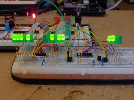
[Osgeld] built himself a binary clock. He didn’t take the time to explain his project, but he did post beautifully hand-drawn schematics and pictures of the circuit (PDF) as he was building it. We’ve seen clock projects that use mains frequency as the clock source and that’s the route that [Osgeld] chose for his build. He started with a 9-12V AC wall wort as a power input. From there it’s just a matter of using a bridge rectifier to convert to DC, then a 7805 linear regulator to establish a steady 5V rail. A resistor and a couple of diodes allow him to pull the 60 Hz frequency off of the incoming AC, and then use a combination of 4000 and 7400 logic chips to count the pulses and keep track of the time.

Wiffletree: A Mechanical Digital To Analog Converter

This isn’t a hack. But it is a decidedly interesting piece of mechanical technology. The Whiffletree shown above is a way to turn binary data into a mechanical analog value. [Bill Hammack] explains how this assembly is used in a typewriter and how a whiffletree can convert binary data to a set of analog outputs.

These linkages are what makes an IBM Selectrix Typewriter work. You know, the one with the globe stylus instead of individual hammers for each key? [Bill] uses the typewriter as the example in his illustrations that show how each bit of data positions the output in a predictably different location. We’re familiar with other mechanical representations of binary data but converting to an analog value mechanically is a new concept for us. Lukily, the videos that [Bill] put together are fantastic at explaining the concepts. Not surprising, since he is a professor at the University of Illinois at Urbana-Champaign . See them both after the break.

Continue reading “Wiffletree: A Mechanical Digital To Analog Converter”

Hackaday Links: November 28, 2010

The Clock Clock

This digital display is made from several analog clocks with thick hands. Together they make something of a 7-segment display, which can be used to display the time. It reminds us of the “Shared Time” installation we covered previously. [Thanks Drum365 via Anonimiss Files]

Quickly desolder lots of parts

[Rhys Goodwin] is grabbing parts from junk PCBs but he’s not using a rework station. Instead it’s a hot-air gun and a brisk tap on the bench to send the parts flying. Well, at least he’s not using a blow-torch like [Ben Heck] does.

Binary Hero

This bank of 8 toggle switches is the controller for Binary Hero, a geeky take on Guitar Hero. When you see a decimal number come down the screen set your toggle to the binary equivalent in time or the game will be over before you know it. [Thanks Fabien]

Quick fan POV

[GMG] took a small persistence of vision board and slapped onto an oscillating fan blade. Along with a couple of magnets on the safety cage this display is a persistence of vision hack you can pull off in an hour or two.

Speed up laser etching

[James] figured out a way to cut down on the time it takes to etch multiple copies of one item with a laser cutter. It doesn’t run the laser faster, but orients the pieces in a way that means less movement of the head while the laser is not on. Read through his article and see if this method can help you out when doing some CNC work.

Hacking A Hack: Disassembly And Sniffing Of IM-ME Binary

It’s fun to pick apart code, but it gets more difficult when you’re talking about binaries. [Joby Taffey] opened up the secrets to one of [Travis Goodspeed’s] hacks by disassembling and sniffing the data from a Zombie Gotcha game binary.

We looked in on [Travis’] work yesterday at creating a game using sprites on the IM-ME. He challenged readers to extract the 1-bit sprites from an iHex binary and that’s what got [Joby] started. He first tried to sniff the LCD data traces using a Bus Pirate but soon found the clock signal was much too fast for the device to reliably capture the signals. After looking into available source code from other IM-ME hacks [Joby] found how the SPI baud rate is set, then went to work searching for that in a disassembly of [Travis’] binary. Once found, he worked through the math necessary to slow down communication from 2.7 Mbit/s to 2400 bps and altered the binary data to match that change. This slower speed is more amenable to the Bus Pirate’s capabilities and allowed him to dump the sprite data as it was sent to the LCD screen.

[Thanks Travis]

Color Clock Makes Telling Time Impossible

[Bogdan] set out to build the all-too-familiar binary clock. But, he didn’t want to be ordinary, and set the goal of making the clock as hard to read as possible. What he ended up with is a clock that is almost impossible to read correctly.
He’s using colors to tell the time. We immediately thought this might make use of resistor codes as the display but it doesn’t. Red shows the hours, green for minutes, and blue for seconds. Now stack all of them on top of each other in binary and you’ve got the time. That means you’ve got to know all of your color combinations, plus read the binary value correctly, to decipher the time. Add to that the display changing every second and we’re in trouble.
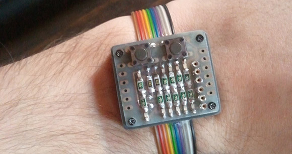
Aside from the user difficulty level, this is a really clean build. It uses an ATmega8535 in conjunction with our favorite DS3232 RTC chip. The etched board is nice and clean, making for an aesthetically pleasing clock.