If you need to regulate your power input down to a reasonable voltage for a project, you reach for a switching regulator, or failing that, an inefficient linear regulator. What if you need to boost the voltage inside a project? It’s boost converter time, and Afrotechmods is here to show you how they work.
In its simplest form, a boost converter can be built from only an inductor, a diode, a capacitor, and a transistor. By switching the transistor on and off with varying duty cycles, energy is stored in the inductor, and then sent straight to the capacitor. Calculating the values for the duty cycle, frequency, inductor, and the other various parts of a boost converter means a whole bunch of math, but following the recommended layout in the datasheets for boost and switching converters is generally good enough.
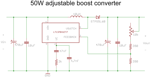
[Afroman]’s example circuit for this tutorial is a simple boost converter built around an LT1370 switching regulator. In addition to that there’s also a small regulator, diode, a few big caps and resistors, and a pot for the feedback pin. This is all you need to build a simple boost converter, and the pot tied to the feedback pin varies the duty cycle of the regulator, changing the output voltage.
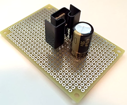
It’s an extremely efficient way to boost voltage, measured by [Afroman] at over 80%. It’s also exceptionally easy to build, with just a handful of parts soldered directly onto a piece of perfboard.
Video below.