Belfry OpenSCAD Library (BOSL2) Brings Useful Parts And Tools Aplenty

OpenSCAD has a lot of fans around these parts — if you’re unaware, it’s essentially a code-based way of designing 3D models. Instead of drawing them up in a CAD program, one writes a script that defines the required geometry. All that is made a little easier with the Belfry OpenSCAD Library (BOSL2).

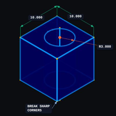
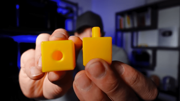
Designing a part like this is a cinch with BOSL2.

BOSL2 has an extensive library of base shapes, advanced functions for manipulating models, and some really nifty tools for creating attachment points on parts and aligning components with one another. If that sounds handy for designing useful objects, you’re in for even more of a treat when you see their functions for gears, hinges, screws, and more.

There’s even one that covers bottle necks and caps. (Those are all standardized by the way, so it’s never been easier to interface to existing bottles or caps in a project.)

OpenSCAD really is very versatile software. It powers useful tools like this screw, washer, and nut generator as well as having more unusual applications like a procedural terrain generator. It’s free, so if you’ve never looked into it, check it out!

Life Without Limits: A Blind Maker’s Take On 3D Printing

In the world of creation, few stories inspire as much as [Mrblindguardian], a 33-year-old who has been blind since the age of two, but refuses to let that hold him back. Using OpenSCAD and a 3D printer, [Mrblindguardian] designs and prints models independently, relying on speech software and touch to bring his ideas to life. His story, published on his website Accessible3D.io, is a call to action for makers to embrace accessibility in their designs and tools.

[Mrblindguardian]’s approach to 3D printing with OpenSCAD is fascinating. Without visual cues, he can still code every detail of his designs, like a tactile emergency plan for his workplace. The challenges are there: navigating software as a blind user, mastering 3D printers, and building from scratch. His tip: start small. Taking on a very simple project allows you to get accustomed to the software while avoiding pressure and frustation.

His successes highlight how persistence, community support, and creativity can break barriers. His journey mirrors efforts by others, like 3D printed braille maps or accessible prosthetics, each turning daily limitations into ingenious innovations. [Mrblindguardian] seems to be out to empower others, so bookmark his page for that what’s yet to come.

Accessible tech isn’t just about empowering. Share your thoughts in the comments if you have similar experiences – or good solutions to limitations like these! As [Mrblindguardian] says on his blog: “take the leap. Let’s turn the impossible into the tangible—one layer at a time”.

Continue reading “Life Without Limits: A Blind Maker’s Take On 3D Printing”

An IPhone Case Study

Way back in 2008, Apple unveiled the first unibody Macbook with a chassis milled out of a single block of aluminum. Before that, essentially all laptops, including those from Apple, were flimsy plastic screwed together haphazardly on various frames. The unibody construction, on the other hand, finally showed that it was possible to make laptops that were both lightweight and sturdy. Apple eventually began producing iPhones with this same design style, and with the right tools and a very accurate set of calipers it’s possible to not only piece together the required hardware to build an iPhone from the ground up but also build a custom chassis for it entirely out of metal as well.

The first part of the project that [Scotty] from [Strange Parts] needed to tackle was actually getting measurements of the internals. Calipers were not getting the entire job done so he used a flatbed scanner to take an image of the case, then milled off a layer and repeated the scan. From there he could start testing out his design. After an uncountable number of prototypes, going back to the CAD model and then back to the mill, he eventually settles into a design but not before breaking an iPhone’s worth of bits along the way. Particularly difficult are the recessed areas inside the phone, but eventually he’s able to get those hollowed out, all the screw holes tapped, and then all the parts needed to get a working iPhone set up inside this case.

[Scotty] has garnered some fame not just for his incredible skills at the precision mill, but by demonstrating in incredible detail how smartphones can be user-serviceable or even built from scratch. They certainly require more finesse than assembling an ATX desktop and can require some more specialized tools, but in the end they’re computers like any other. For the most part.

Continue reading “An IPhone Case Study”

Optical illusion gingerbread house from an odd perspective

An Engineer’s Perspective On Baking Gingerbread Houses

If you’ve ever wanted to merge the worlds of holiday cheer and clever geometry, [Kris Wilk]’s gingerbread house hack is your ultimate inspiration. Shared in a mesmerising video, [Wilk] showcases his 2024 entry for his neighborhood’s gingerbread house contest. Designed in FreeCAD and baked to perfection, this is no ordinary holiday treat. His pièce de résistance was a brilliant trompe l’oeil effect, visible only from one carefully calculated angle. Skip to the last twenty seconds of the video to wrap your head around how it actually looks.

[Wilk] used FreeCAD’s hidden true perspective projection function—a rarity in CAD software. This feature allowed him to calculate the perfect forced perspective, essential for crafting the optical illusion. The supporting structures were printed on a Prusa MK4, while the gingerbread itself was baked at home. Precision photography captured the final reveal, adding a professional touch to this homemade masterpiece. [Wilk]’s meticulous process highlights how accessible tools and a sprinkle of curiosity can push creative boundaries.

For those itching to experiment with optical illusions, this bakery battle is only the beginning. Why not build a similar one inside out? Or construct a gingerbread man in the same way? Fire up the oven, bend your mind, and challenge your CAD skills!

Continue reading “An Engineer’s Perspective On Baking Gingerbread Houses”

Zero To Custom MacroPad In 37 Easy Steps

[Jeremy Weatherford] clearly has a knack for explaining projects well enough for easy reproduction but goes way further than most and has created a four-part YouTube series detailing every step from project inception to the final assembly, covering all aspects of 3D modelling and PCB design for a custom MacroPad design. Many tools are introduced along the way, all of which help reduce complexity and, by extension, the scope for errors. As every beginner hacker knows, early successes breed confidence and make for better and more ambitious projects.

Part 1 covers the project motivation and scope and introduces a keyboard layout editor tool. This tool allows one to take a layout idea and generate a JSON file, which is then used to drive keyboard tools. XYZ to produce a usable KiCAD project. The tool only generates a PCB project and an associated netlist file. No schematic is created; you don’t need one for a simple layout.

A very basic keyboard layout

Part 2 is a walkthrough of the design process in KiCAD, culminating in ordering the PCB from JLCPCB and assembling the surface-mount parts. This particular design uses a controller based on the Sea-Picro RP2040 module, but there are many options if you have other preferences. [Jeremy] shows what’s possible with the selected suppliers, but you need not follow this step precisely if you have other ideas or want to use someone local.

Part 3 covers exporting the mechanical aspects of the PCB out of KiCAD and into a 3D CAD program, specifically OnShape. [Jeremy] covers some crucial details, such as how to read the mechanical drawing of the keys to work out where to place the top plate. It’s very easy to plough straight in at this stage and make a design which cannot be assembled! The plan is to use a simple laser-cut box with a bottom plate with mounting holes lining up with those on the PCB. A Top plate is created by taking the outline of the PCB and adding a little margin. An array of rectangular cutouts are designed for the keys to protrude, lining up perfectly with where the keys would be when mounted on the PCB below.  The sides of the case are formed from laser-cut sections that lock into each other and the laser-cut base—using the laser joint feature-script addon tool from the OnShape community channel. A second feature script addon is used to auto-layout the laser-cut components onto a single sheet. A CAM application called Kiri Moto is used to export for laser cutting and is available on the OnShape store.

Continue reading “Zero To Custom MacroPad In 37 Easy Steps”

CADmium Moves CAD To The Browser

For plenty of computer users, the operating system of choice is largely a middleman on the way to the browser, which hosts the tools that are most important. There are even entire operating systems with little more than browser support, under the assumption that everything will be done in the browser eventually. We may be one step closer to that type of utopia as well with this software tool called CADmium which runs exclusively in a browser.

As the name implies, this is a computer-aided design (CAD) package which looks to build everything one would need for designing project models in a traditional CAD program like AutoCAD or FreeCAD, but without the burden of needing to carry local files around on a specific computer. [Matt], one of the creators of this ambitious project, lays out the basic structure of a CAD program from the constraint solver, boundary representation (in this case, a modern one built in Rust), the history tracker, and various other underpinnings of a program like this. The group hopes to standardize around JSON files as well, making it easy to make changes to designs on the fly in whatever browser the user happens to have on hand.

While this project is extremely early in the design stage, it looks like they have a fairly solid framework going to get this developed. That said, they are looking for some more help getting it off the ground. If you’ve ever wanted something like this in the browser, or maybe if you’ve ever contributed to the FreeCAD project and have some experience, this might be worth taking a look at.

Throw FreeCAD Some Curves

[Mango Jelly] got a question from someone trying to model a phone box with a complex curved roof. We have to admit that when we saw it, we knew it would be hard to model well. Naturally, there are several ways it could be one, but [Mango Jelly] used the curves workbench in FreeCAD to produce a wireframe of the shape, and you can see how that works in the video below.

The curve bench didn’t sound familiar to us, and that’s because it is an add-on workbench. He starts with a sketch of a curve, constrained to be symmetrical. Then the draft workbench allowed a rotation to convert the curve into a nice skeleton of the curved roof.

The curves workbench can create a Gordon surface over that skeleton. You can extrude that into a solid object. There are still some details to add, though, and you’ll see how each part of the roof takes shape.

Watching videos like this reminds us that we use a small fraction of what FreeCAD can do. You’ll probably pick up at least one tip from this video. If you need a quick basic tutorial, try the one from [NovaSpirit]. Or, try a longer one.

Continue reading “Throw FreeCAD Some Curves”