Figuring out the maximum number of peripherals which can be sensed or controlled with a minimum number of IOs is a classic optimization trap with a lot of viable solutions. The easiest might be something like an i2c IO expander, which would give you N outputs for 4 wires (SDA, SCL, Power, Ground). IO expanders are easy to interface with and not too expensive, but that ruins the fun. This is Hackaday, not optimal-cost-saving-engineer-aday! Accordingly there are myriad schemes for using high impedance modes, the directionality of diodes, analog RCs, and more to accomplish the same thing with maximum cleverness and minimum part cost. Tucoplexing is the newest variant we’ve seen, proven out by the the prolific [Micah Elizabeth Scott] (AKA [scanlime]) and not the first thing to be named after her cat Tuco. 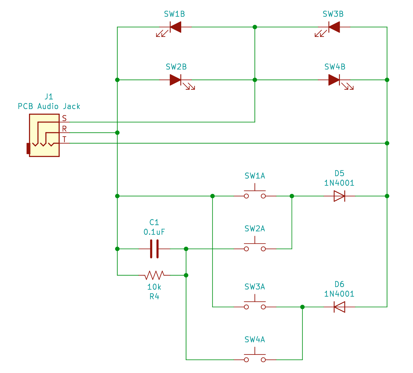
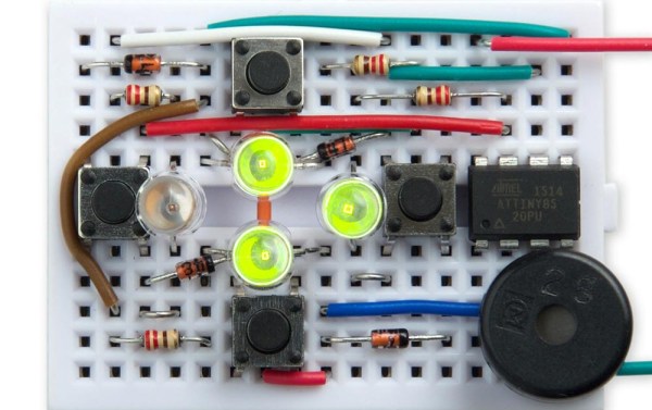
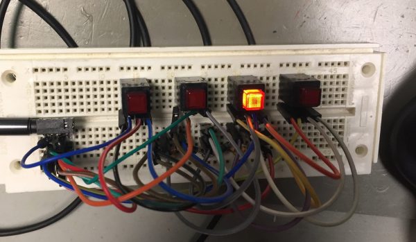
[Micah’s] original problem was that she had a great 4 port USB switch with a crummy one button interface. Forget replacement; the hacker’s solution was to reverse and reprogram the micro to build a new interface that was easier to relocate on the workbench. Given limited IO the Tucoplex delivers 4 individually controllable LEDs and 4 buttons by mixing together a couple different concepts in a new way.
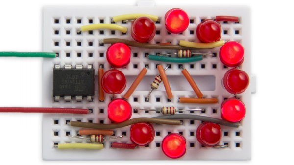
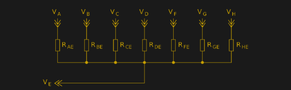
Up top we have 4 LEDs from a standard 3 wire Charlieplex setup. Instead of the remaining 2 LEDs from the 3 wire ‘plex at the bottom we have a two button Charlieplex pair plus two bonus buttons on an RC circuit. Given the scary analog circuit the scan method is pleasingly simple. By driving the R and T lines quickly the micro can check if there is a short, indicating a pressed switch. Once that’s established it can run the same scan again, this time pausing to let the cap charge before sensing. After releasing the line if there is no charge then the cap must have been shorted, meaning that switch was pressed. Else it must be the other non-cap switch. Check out the repo for hardware and firmware sources.
Last time we talked about a similar topic a bunch of readers jumped in to tell us about their favorite ways to add more devices to limited IOs. If you have more clever solutions to this problem, leave them below! If you want to see the Twitter thread with older schematics and naming of Tucoplexing look after the break.
Continue reading “Tucoplexing: A New Charliplex For Buttons And Switches”