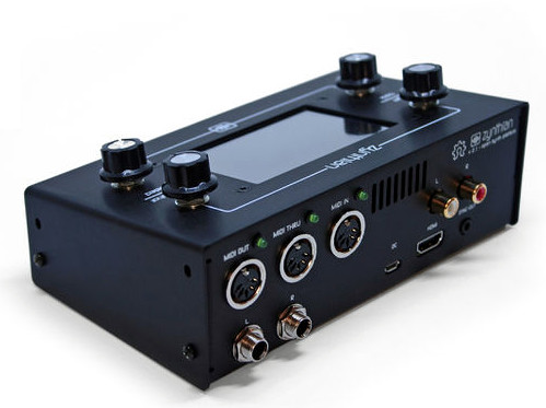
Have you ever seen something and instantly knew it was something you wanted, even though you weren’t aware it existed a few seconds ago? That’s how we felt when we received a tip about Zynthian, a fully open source (hardware and software) synthesizer. You can buy the kit online directly from the developers, or build your own from scratch using their documentation and source code. With a multitude of filters, effects, engines, and essentially unlimited upgrade potential, they’re calling it a “Swiss Army Knife of Synthesis”. We’re inclined to agree.
At the most basic level, the Zynthian is a Raspberry Pi 3 with a touch screen, a few rotary encoders, a dedicated sound card, and MIDI support. Software wise the biggest feature is arguably the real-time Linux kernel for the lowest latency possible. There’s also a custom web interface so you can control the Zynthian from another machine on the network if you want. As a matter of course, it also includes a wide array of pre-installed audio packages to experiment and create with.
Kits are offered at various prices from $420 USD for the top of the line model down to unpopulated PCBs for a few bucks. We like that they broke things down this way; allowing users of various skill (and or patience) to pay what they want. If you just want to buy the custom boards and roll your own case and Pi solution, you can do that.
If you want to go all in, you can build one entirely from scratch as well. Everything from the CAD files for the case to their custom rotary encoder library is completely open (most licensed under GPL v3) for anyone to use however they see fit. There’s even a page in the wiki for listing hardware which isn’t officially supported by the project, but remain as options for those looking to cut their own path.
For those of us who grow up around natural swimming holes, algae are the reason we have to wash after taking a dip. Swimmer’s itch* or just being covered in green goop is not an attractive way to spend an afternoon. Lumping all algae together is not fair, some of it is nasty but some of it is delicious and humans have been eating it for generations.
If you are thinking that cases of algae cuisine are not widespread and that algae does not sound appealing, you are not alone. It is a tough sell, like convincing someone to try dandelions for the first time. It may not warrant a refrigerator section in the grocery store yet, but algae can produce protein-rich food which doesn’t require a lot of processing.
Currently, there is a lot of work to be done to bring up the efficiency of algae farms, and Qualitas has already started. The leaps they are making signify just how much room we have for improvement. The circulating paddle wheels, which can be seen in the video below the break, use one-third of the energy from their previous version. Their harvester uses one-thirtieth! Right now, their biggest cost comes from tanks of carbon dioxide, which seems off given that places such as power plants pay to get rid of the stuff. That should give some food for thought.
Putting everything on the Internet is getting easier and easier, what with the profusion of Internet-ready appliances as well as cheap and plentiful IoT modules to integrate legacy devices. Think IoT light bulbs, refrigerators and dishwashers that can be controlled from a smartphone, and the ubiquitous Sonoff modules. But once these things are on the net, what are they talking about? Are they saying things behind your back? Are they shipping data about your fridge contents off to some foreign land, to be monetized against your will?
Maybe, maybe not, but short of a tinfoil helmet the only way to protect yourself is to build your own system. This IoT control for ceiling fans is a good example, with the added benefit that most wireless ceiling fan remotes are kind of lousy. [microentropie] didn’t like the idea of going the Sonoff route, so his custom controller is based on that IoT workhorse, the ESP8266. There are two versions, one switching the light and fan loads with relays, and one with triacs. The ESP serves up its own web page for control rather than using a cloud service, and is capable of setting up the fan to turn on and off automatically at preset times or temperatures. Everything sits in an unobtrusive box on the ceiling near the fan, but we bet this could be miniaturized enough to fit right inside the fan housing.
If some of [microentropie]’s code looks familiar, it might be because he borrowed it from his IoT rice cooker project.
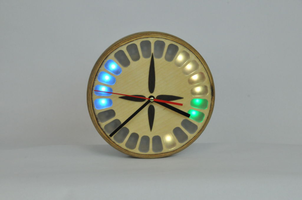
Now that most of what we do revolves around our phones and/or the internet, it’s nearly impossible to take a short break from work to check the ol’ calendar without being lured by the sirens on the shore of social media. Well, [samvanhook] was tired of being drawn in when all he really needs is a vague idea of what’s coming up for him in the next 12 hours. Enter the CalClock.
Thanks to color-coded segments, [sam] can tell at a glance if he has something coming up soon in Google Calendar, or if he can dive back into work. When nothing is scheduled, the segments are simply unlit.
We love the mid-century minimal look and craftsmanship of CalClock. This beauty runs on a Raspi Zero W, which fetches the 411 through the gooCal API and lights up the appropriate NeoPixels arrayed behind standard clock movement-driven hands. [sam] could have diffused the NeoPixels with a single sheet of acrylic, but he went the extra mile to route and sand little acrylic ice cubes for all 24 segments.
One of the great unsolved problems in the world of DIY electronics is a small keyboard. Building your own QWERTY keyboard is a well-studied and completely solved problem; you need only look at the mechanical keyboard community for evidence of that. For a small keyboard, though, you’d probably be looking at an old Blackberry handset, one of those Bluetooth doohickies, or rolling your own like the fantastic Hackaday Belgrade badge. All of these have shortcomings. You’ll need to find a header for the Blackberry keyboard’s ribbon cable, the standard Bluetooth keyboard requires Bluetooth, and while the Belgrade badge’s keyboard works well, it’s a badge, not a keyboard you would throw in a bag for years of use.
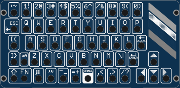
[bobricious] might have just cracked it. For his Hackaday Prize entry, he’s created a tiny USB keyboard out of tact switches. What’s the secret? An entire panel of PCBs. It looks great, and it might just hold up to the rigors of being tossed in a random bag of holding filled with electronics.
The electronics for the keyboard are simple enough; there are 56 standard through-hole tact switches, and an SAMD21 microcontroller. Connections to the outside world are through a micro USB port, serial, or I2C. it’s small, too, coming in at just under 5 cm by 10 cm.
The real trick here is using a stack of PCBs to label the buttons and provide a bit of mechanical support. The panel for this project consists of one base board holding all the electronics and a secondary board that gives the entire project a finished look while adding a bit of structural support.
If you’ve never looked at the options for small keyboards, there aren’t many. Blackberries are a thing of the past, and there’s no good way to add a QWERTY keyboard to small projects. This project does that in spades. Since the basic idea is, ‘put holes in a second PCB’, this idea is transferable to other keyboard layouts too.
The 2N3819 is the archetypal general-purpose N-channel FET. (ON Semiconductor)
Over the recent weeks here at Hackaday, we’ve been taking a look at the humble transistor. In a series whose impetus came from a friend musing upon his students arriving with highly developed knowledge of microcontrollers but little of basic electronic circuitry, we’ve examined the bipolar transistor in all its configurations. It would however be improper to round off the series without also admitting that bipolar transistors are only part of the story. There is another family of transistors which have analogous circuit configurations to their bipolar cousins but work in a completely different way: the Field Effect Transistors, or FETs.
In a way it’s less pertinent to look at FETs in the way we did bipolar transistors, because while they are very interesting devices that power much of what you will do with electronics, you will encounter them as discrete components surprisingly rarely. Every CMOS device you deal with relies on FETs for its operation and every high-quality op-amp you throw a signal at will do so through a FET input, but these FETs are buried inside the chip and you’d be hard-pressed to know they were there if we hadn’t told you. You’d use a FET if you needed a high-impedance audio preamp or a low-noise RF amplifier, and FETs are a good choice for high-current switching applications, but sadly you will probably never have a pile of general-purpose FETs in the way you will their bipolar equivalents.
That said, the FET is a fascinating device. Join us as we take an in-depth look at their operation, and how and where you might use one.
FET basics
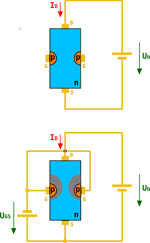
A diagram of an n-channel JFET. As the negative gate voltage on the p-type silicon decreases in the lower diagram, its electric field restricts the area through which electrons can flow in the n-type channel. Chtaube,(CC BY-SA 2.0 DE)
A basic FET has three terminals, a source (the source of electrons), a gate (the control terminal), and a drain (where electrons leave the device). These are analogous to the terminals on a bipolar transistor, in that the source fulfills a similar role to the emitter, the gate to the base, and the drain to the collector. Thus the three basic bipolar transistor circuit configurations have equivalents with a FET; common-emitter becomes common-source, common-base becomes common-gate, and an emitter follower becomes a source follower. It is dangerous to stretch the analogy between bipolar transistors and FETs too far, though, because of their different mode of operation. A closer similarity exists between a FET and a triode tube, if that helps.
The simplest FET for demonstration purposes has a piece of N-type semiconductor with source and drain connections at opposite ends, and a zone of P-type semiconductor deposited in its middle. This is referred to as an N-channel junction FET or JFET, because the channel through which current flows is N-type semiconductor, and because a diode junction exists between gate and channel. There are equivalent P-channel devices, just as there are PNP and NPN bipolar transistors.
Were you to bias an n-channel JFET as you would a bipolar transistor with a positive bias on its gate, the diode between gate and source would conduct, and the transistor would remain a diode with two cathode terminals. If however you give the gate a negative bias compared to the source, the diode becomes reverse-biased, and no current to speak of flows in the gate.
A characteristic of a reverse-biased diode is that it has a depletion zone between anode and cathode, an area in which there are no electrons. This is what causes the diode to no longer conduct, and the size of the depletion zone depends upon the size of the electric field that exists across it. If you’ve ever used a varicap diode, the capacitance between the two sides of this variable-width zone is the property you are exploiting.
In a FET, the depletion zone stretches from the gate region into the channel, and since its size can be adjusted by the gate voltage it can be used to “pinch” the remaining conductive region within the channel. Thus the area through which electrons can flow is controlled by the gate voltage, and thus the current that flows between drain and source is proportional to the gate voltage. We have an amplifier.
A simple FET radio receiver circuit showing FET biasing. The gate is biased at ground potential through the inductor, and the source is held above ground by the current in the 5K resistor. Herbertweidner [Public domain].In the JFET diagram above, the negative gate bias is represented by a battery. Tube enthusiasts may have encountered equipment that derives negative grid bias from a power supply, and you will find tube power units that include a -150 V rail for this purpose. In general though this is inconvenient in a FET circuit even though the voltage is lower, because of the extra cost of a negative regulator.. Instead the gate is held at a lower potential than the source by careful selection of a source resistor such that the current flowing through it brings the source up above ground, and a gate bias circuit that holds the gate close to ground. The base resistor chain from the bipolar circuit is for this reason often replaced with either a single resistor to ground, or a gate circuit with a very low DC resistance to ground such as an inductor.
MOSFETs, where the FET becomes more useful
Internal structure of an N-channel MOSFET. Fred the Oyster [Public domain].The JFET we have described is the simplest of field-effect devices, but it is not the one you will encounter most frequently. MOSFETs, short for Metal Oxide Semiconductor FETs, have a similar source, gate, and drain, but instead of relying on a depletion zone in a reverse-biased diode, they have a thin layer of insulation. The electric field from the gate acts across this insulation and pinches the conductive region in the channel through repulsion of electrons, with the same effect as it has in the JFET. It is beyond the scope of this piece to go into their mechanisms, but you will encounter two types of MOSFET: depletion mode devices that require the same negative bias as the JFET, and enhancement mode MOSFETS that require a positive bias.
Why would you use a FET?
So we’ve described the FET, and noted that while its mode of operation is different to that of a bipolar transistor it does a substantially similar job. Why would we use a FET then, what advantages does it offer us? The answer comes from the gate being insulated either by a depletion region in a JFET or by an insulating layer in a MOSFET. A FET is a voltage amplifier rather than a current amplifier, its input impedance is many orders higher than that of a bipolar transistor, and thus you will find FETs used in many applications that require a high impedance small-signal amplifier. The input of a high-performance op-amp will almost certainly be a FET, for example.
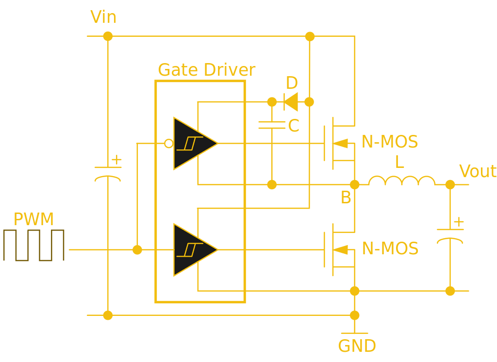
This half-bridge power MOSFET driver circuit uses a specialist gate driver IC with a pair of Schmidt buffers to deliver the initial surge required for a fast-turn-on time. Wdwd (CC BY 3.0).
The high input impedance has another effect less coupled to small signal work. Where a bipolar transistor requires significant base current to turn itself on, the corresponding FET requires almost none. Thus almost all complex integrated circuit logic devices are FET-based rather than bipolar because of the huge power saving that can be made by not needing to supply the base current demands of many thousands of bipolar transistors.
The same effect influences the choice of FETs for power switching, while a bipolar transistor’s base current is proportional to its collector current and thus it will need a significant driver, by contrast a power MOSFET requires virtually no standing gate current after an initial surge. A MOSFET power switch can thus be built requiring much less in the way of drive electronics and much more efficiently than a corresponding bipolar switch, and makes possible some of the tiny driver boards you might be used to for driving motors in your 3D printer, or your multirotor.
Through the course of this series you should have acquired a solid grounding in basic bipolar transistor principles, and now you should be able to add FETs to that knowledge base. We suggested you buy a bag of 2N3904s to experiment with in one of the previous articles, can we now suggest you do the same with a bag of 2N3819s?
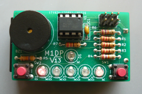
What makes a game a game? Like, how do we know that we’re looking at a variation of PONG when confronted with one? And how do we know how to play it? [Bertho] sought to answer this question as he designed what is probably the smallest-ever 1-D PONG game. His answer involves charlieplexing LEDs, using a voltage divider to save I/O pins, and a couple of AAAs that should last for a long, long time.
[Bertho]’s Minimum 1-D PONG, or m1dp for short, puts an ATTiny85 through its paces as gameplay quickly progresses from ‘I got this’ to ‘no one could possibly keep this up’. This state machine sleeps until one of the two buttons is pressed, at which time a wait animation starts. The action begins with the next button press.
Game play across only five LEDs makes for some pretty intense action, too. Fortunately, the buzzer is a big part of the experience. It sounds one tone for each LED when the ball is in play, and a different tone to confirm button presses. [Bertho] saved so many I/O pins with charlieplexing that he added a green LED that lights up when it’s OK to return the ball. If we were playing, we’d keep our eye on this LED instead of trying to watch the ball. We’re serving the demo after the break point, so don’t let it get past you.
For a study in minimalism, there sure is a lot going on here with all the different tones and animations. If you’d prefer maximalist 1-D PONG, there’s always LED strips. If dungeon crawlers with satisfying hardware are more your thing, you really need to check out Twang.

 At the most basic level, the Zynthian is a Raspberry Pi 3 with a touch screen, a few rotary encoders, a dedicated sound card, and MIDI support. Software wise the biggest feature is arguably the real-time Linux kernel for the lowest latency possible. There’s also a custom web interface so you can control the Zynthian from another machine on the network if you want. As a matter of course, it also includes a wide array of pre-installed audio packages to experiment and create with.


![A simple FET radio receiver circuit showing FET biasing. The gate is biased at ground potential through the inductor, and the source is held above ground by the current in the 5K resistor. Herbertweidner [Public domain].](https://hackaday.com/wp-content/uploads/2018/06/1kreiser_mit_fet.png)
![Internal structure of an N-channel MOSFET. Fred the Oyster [Public domain].](https://hackaday.com/wp-content/uploads/2018/04/n-channel_mosfet-svg1.png)