Thrust Vectoring With Compliant Mechanisms Is Hard

Thrust vectoring is one way to control aerial vehicles. It’s become more popular as technology advances, finding applications on fifth-generation fighter aircraft, as well as long being used in space programmes the world over.[RCLifeOn] decided to try and bring the technology to a prop-powered RC aircraft, in an unconventional way.

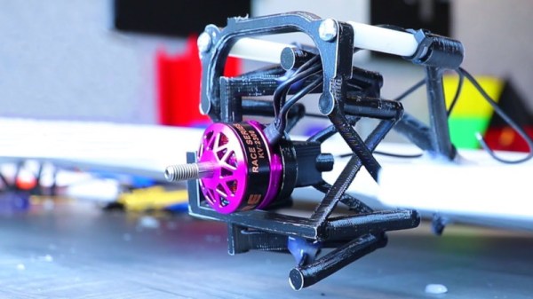
After attending a lecture on compliant mechanisms and their potential use in space vehicles for thrust vectoring control, [RCLifeOn] decided to try applying the concept himself. His test mechanism is a fixed-wing with a single-piece motor mount that has enough flex in the right places to allow the motor (and propeller) to be moved in two axes, achieving thrust vectoring control.

After printing a compliant motor mount in a variety of materials, one was selected for having the right balance of strength and flexibility. The vectoring mechanism was fitted to a basic flying wing RC aircraft, and taken to the field for testing. Unfortunately, success was not the order of the day. While the mechanism was able to flex successfully and vector the motor in bench testing, it was unable to hold up to the stresses of powered flight. The compliant mechanism failed and the plane nosedived to the ground.

[RCLifeOn] suspects that the basic concept is a difficult proposition to engineer properly, as adding strength would tend to add weight which would make flight more difficult. Regardless, we’d love to see further development of the idea. It’s not the first time we’ve seen his 3D-printed flight experiments, either. Video after the break.

Continue reading “Thrust Vectoring With Compliant Mechanisms Is Hard”

Evolving The 3D Printed Linear Actuator

Our open source community invites anyone with an idea to build upon the works of those who came before. Many of us have encountered a need to control linear motion and adapted an inexpensive hobby servo for the task. [Michael Graham] evaluated existing designs and believed he has ideas to advance the state of the art. Our Hackaday Prize judges agreed, placing his 3D Printed Servo Linear Actuator as one of twenty winners of our Robotics Module Challenge.

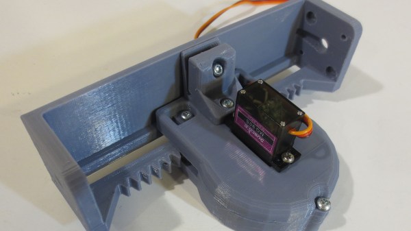
[Michael]’s actuator follows in the footstep of other designs based on a rack-and-pinion gear such as this one featured on these pages, but he approached the design problem from the perspective of a mechanical engineer. The design incorporated several compliant features to be tolerant of variances between 3D printers (and slicer, and filament, etc.) Improving the odds of a successful print and therefore successful projects. Beginners learning to design for 3D printing (and even some veterans) would find his design tips document well worth the few minutes of reading time.

Another useful feature of his actuator design is the 20mm x 20mm screw mounting system. Visible on either end of the output slider, it allows mixing and matching from a set of accessories to be bolted on this actuator. He is already off and running down this path and is facing the challenge of having too many things to share while keeping them all organized and usable by everyone.

The flexible construction system allows him to realize different ideas within the modular system. He brought one item (a variant of his Mug-O-Matic) to the Hackaday + Tindie Meetup at Bay Area Maker Faire, and we’re sure there will be more. And given the thoughtful design and extensive documentation of his project, we expect to see his linear servos adopted by others and appear in other contexts as well.

This isn’t the only linear actuator we’ve come across. It isn’t even the only winning linear actuator of our Robotics Module Challenge, but the other one is focused on meeting different constraints like compactness. They are different tools for different needs – and all worthy additions to our toolbox of mechanical solutions.

Ask Hackaday: What Can You Do With Origami?

At some point, most of us have learned a little of the ancient art of origami. It’s a fascinating art form, and being able to create a recognizable model by simply folding paper in the right order can be hugely satisfying. Most of us move on to other pursuits once we master the classic crane model, but the mathematics behind origami can lead some practitioners past the pure art to more practical structures, like this folding ballistic barrier for law enforcement use.

The fifty-pound Kevlar and aluminum structure comes from Brigham Young University’s College of Mechanical Engineering, specifically from the Compliant Mechanisms Research program. Compliant mechanisms move by bending or deflecting rather than joints between discrete parts, and this ballistic shield is a great example. The mechanism is based on the Yoshimura crease pattern, which can be quickly modeled with a piece of paper. Scaling that up to a full-sized structure, light enough to be fielded but strong enough to stop a .44 Magnum round, was no mean feat. But as the video below shows, the prototype has a lot of potential.

Now it’s your turn: what applications have you seen for compliant mechanisms? Potential applications range in scale from MEMS linkages for microinjecting cells to huge antennas that unfurl in orbit. We’ve featured a few origami-like structures before, like this self-assembling robot or a folding quadcopter, but neither of these really rates as compliant. This elegant parabolic satellite antenna is more like it, though. There are applications for designing origami and a mathematical basis for the field; has anyone tried using these tools to design compliant structures? Sound off in the comments below.

Continue reading “Ask Hackaday: What Can You Do With Origami?”