It’s no secret that we think flexures are pretty cool, and we’ve featured a number of projects that leverage these compliant mechanisms to great effect. But when we saw flexures used in a six-DOF positioner with micron accuracy, we just had to dig a little deeper.
The device is known as the Hexblade, and it comes to us from the lab of [Jonathan Hopkins] at UCLA. We have to admit that at times, the video below feels a little like
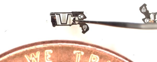
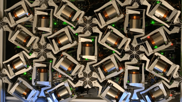
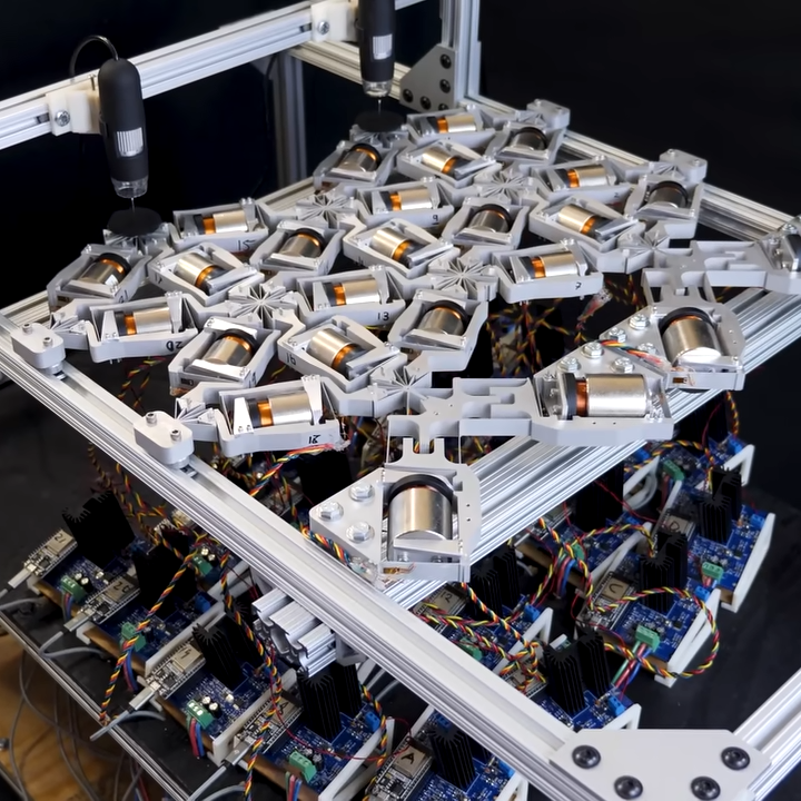
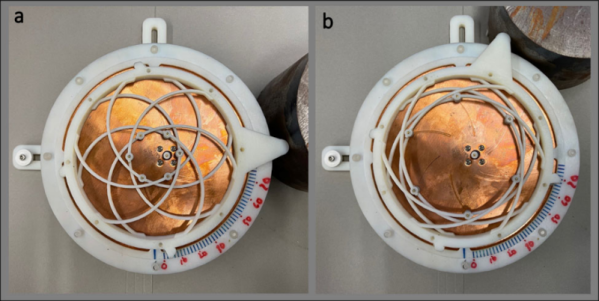
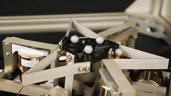
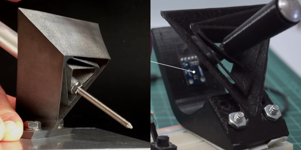
the “Turbo Encabulator” schtick — “three identical decoupled actuation limbs arranged in an axisymmetric configuration” may be perfectly descriptive, but it does not flow trippingly from the tongue. Hats off to [Professor Hopkins] for nailing the narration, though, and really, once you get a handle on the jargon, it all makes perfect sense. The platform is supported by a total of six flexures, which look like bent pieces of sheet metal but are actually cut from a solid block of material using wire EDM. Three of the flexures are oriented in the plane of the platform, while the other three are perpendicular to it. The far end of each flexure is connected to a voice-coil actuator that is surrounded by another flexure, this one in a parallelogram arrangement. The six actuators can move the platform smoothly through three linear translations (X, Y, and Z) and three rotations (roll, pitch, and yaw).
The platform’s range of motion is limited, but the advantages of using flexures as bearings are clear — there’s no backlash or hysteresis, and the voice coils can control the position of the stage to micron accuracy. Something like the Hexblade would be an ideal positioner for microscopy, and we can imagine an even smaller version, perhaps even a MEMS-fabricated one for nanomanufacturing applications. The original concept of the Hexblade serving as the print head for a fabrication robot for space applications is pretty cool, too, and we’d venture to say that a homebrew version of this probably isn’t out of reach either.
Continue reading “Flexures Make This Six-DOF Positioner Accurate To The Micron Level” →