From Reference Design To USB Sound Card

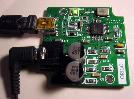
[Entropia] decided to try his hand at rolling is own sound card. He picked out a DAC chip, started his prototyping by studying the reference design from the datasheet, then went through several iterations to arrive at this working model.

He chose to base the board around the PCM2706. It’s a digital to analog converter that has built-in USB support; perfect for his needs. It’s got a headphone amplifier, but is also capable of putting out S/PDIF signals for a digital amplifier to pick up and use. Not bad for a part that can be had for right around eight bucks.

The first PCB he designed had a few electrical and footprint errors. But he was able to get it to run by adding some point-to-point jumpers, and bending the legs of his capacitors to fit the board area. With those issued accounted for he ordered a second batch of boards. These went together nicely, but the headphone output was incredibly loud. Turns out the filtering circuit had the wrong resistor and capacitor values. Changing them around, and swapping the audio output so that the correct channels were patched to the audio jack brings it to the first release version seen above.

Playing MP3s From An FPGA

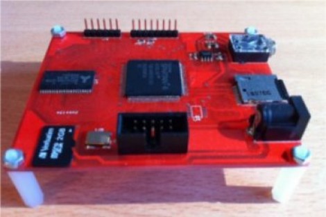
Building an audio player is a fun project. It used to be quite a task to do so, but these days the MP3 decoder chips are full-featured which means that if you know how to talk to other chips with a microcontroller you’ve got all the skills needed to pull off the project. But that must have been too easy for [Ultra-Embedded], he decided just to build an MP3 player out of an FPGA.

It’s not quite as difficult as it first sounds. He didn’t have to figure out how to decode the audio compressions. Instead he rolled the Helix MP3 decoder library into the project. It had already been optimized to run on an ARM processor, and since he’s using a RISC soft processor the translation wasn’t tough at all. He’s using a 24-bit stereo DAC chip to bridge the gap between the audio jack and the FPGA output. Clocking that chip with the FPGA isn’t ideal and causes 44.1 kHz audio to run 3% too slow. He says it’s not noticeable, which we believe. But if you try to play along with a song the pitch shift might end up driving you crazy.

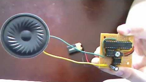
If you’d prefer to just stick to the microcontroller based players this one’s small and inexpensive.

Dabbling With CPLD Generated VGA Signals

It seems like all the cool kids are leaving the 8-bit hobby microcontrollers in the parts bin and playing with more advanced parts like Complex Programmable Logic Devices. [Chris] is no exception to the trend, and set out to generate his own VGA signal using one of the beefy semiconductors.

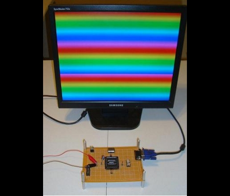
It seems that he’s using the acronyms CPDL and FPGA interchangeable in his post but according to the parts list this setup uses an Altera EPM7128SLC84-7N CPLD. In order to generate the VGA signal he needed a way to convert the digital signals from the chip into the analog values called for in the video standard. He chose to build a Digital Analog Converter for the RGB color values using a resistor network which he calculated using PSpice. The other piece in the puzzle is a 25.175 MHz oscillator to clock the CPLD. As you can see after the break, his wire-wrapped prototype works exactly as designed. The example code generates the rainbow bars seen above, or a bouncing box demo reminiscent of a DVD player screen saver.

Want to know more about programming CPLDs? We did a tutorial on the subject a while back.

Continue reading “Dabbling With CPLD Generated VGA Signals”

Your First Digital To Analog Converter Build

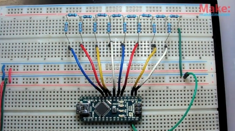
Have you ever built a Digital to Analog Converter before? This is a circuit that can take the 0 or 5V coming off of several digital logic pins, combine them together, and spit out one analog voltage that represents that value. If you’ve never made one, here’s your chance. [Collin Cunningham] over at Make put together another lab video about DACs which we’ve embedded after the break.

The circuit above uses an R-2R resistor network – often called a resistor ladder – which you can learn much more about from the reference page that [Collin] links to. Although a DAC in an IC package is by far the most commonly found application, we do see these R-2R networks in audio hacks from time to time.

Continue reading “Your First Digital To Analog Converter Build”

Intro To Circuit Bending

Electronic musical instruments are a lot of fun for a hacker because, with a small palette of tools, know-how and curiosity, they are easily modified. As with any hack, there is always the chance that the subject will be ruined, so it’s not necessarily worth the risk to muck about inside your thousand-dollar pro synthesizer. Luckily for all of us, there are shovel-fulls of old electronic musical toys littering the curbs and second-hand shops of the world. These fun little devices provide ample opportunity to get familiar with audio electronics and circuit bending techniques.

A note on definitions: the term “circuit bending” can be synonymous with “hardware hacking” in the world of audio electronics, and we have seen some debate as to which term is better suited to a given project. We welcome you to share your viewpoints in the comments.

Keep reading to get started.
Continue reading “Intro To Circuit Bending”

Android Talks Pulsewave

Serial communications are a mainstay of digital computing. They don’t require much physical infrastructure and they exist in variations to fit almost any application. The behaviour of serial communications lines, varying from high to low voltage in a timed pattern, is analogous to a 1-bit DAC. Using a whole DAC for serial communication would be a waste in most cases, but the [RobotsEverywhere] team found an exception which you may have encountered already.

Since the audio output of the Android is accessible and addressable, [RobotsEverywhere] wrote source code to use the left and right channels as separate serial communication lines. This circumvents the need to bust into the device and muck about with the hardware which is great if you want a no-risk hack that allows communications to an RS232 port. Any hardware on which you can write to the DAC (and control the sampling rate) is a potential target.

There are some external electronics required to convert the audio signal to TTL, but it’s not very complicated–a couple of comparators and change. You can see it in action after the break.

As a bonus, when you’re done for the day you can plug in your headphones and listen to the soothing poetry of pulse waves all night long.

Continue reading “Android Talks Pulsewave”

PIC Programmable Power Supply

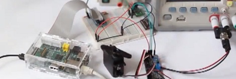
This programmable power supply is the perfect addition to your bench tools. [Debraj Deb], who previously built a whole house power monitor, designed this build around a PIC 18F4520 microcontroller. The desired voltage is set with an attached keypad, resulting in a digital output on the 8-bits of port D. The port connects to another protoboard with an R-2R digital-to-analog converter resulting in the target voltage. A set of transistors amplifies the current and a power transistor then takes care of the final output. After the break you’ll find two videos, the first walks us through the hardware and the second demonstrates the device in action, along with measurements of its performance. This certainly provides a lot more functionality than an ATX power-supply conversion.

Update: A big thanks to [Debraj] who sent us a code package as well as the schematic (PDF) used during testing. We’re having trouble getting the code package up for download right now. Check back later, hopefully we’ll have it up soon.

Continue reading “PIC Programmable Power Supply”