Lighting Tech Dives Into The Guts Of Laser Galvanometers

There’s something magical about a laser light show. Watching that intense beam of light flit back and forth to make shapes and patterns, some of them even animated, is pretty neat. It leaves those of us with a technical bent wondering just exactly how the beam is manipulated that fast.

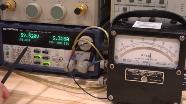
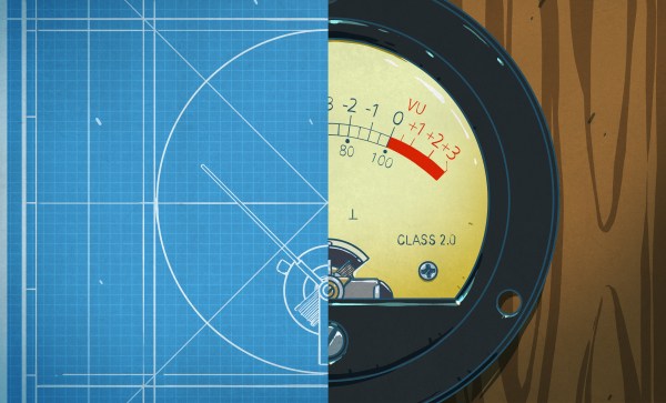
Wonder no more as [Zenodilodon], a working concert laser tech with a deep junk bin, dives into the innards of closed-loop galvanometers, which lie at the heart of laser light shows. Galvos are closely related to moving-coil analog meters, which use the magnetic field of a coil to deflect a needle against spring force to measure current. Laser galvos, on the other hand, are optimized to move a lightweight mirror back and forth, by tiny amounts but very rapidly, to achieve the deflection needed to trace out shapes.

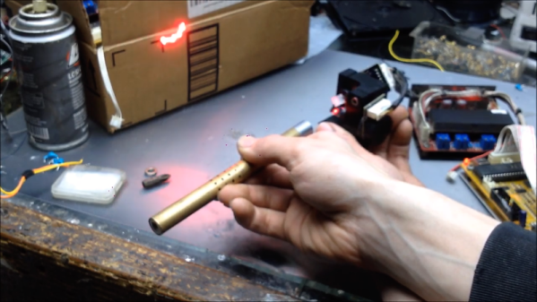
As [Zeno] explains in his teardown of some galvos that have seen better days, this means using a very low-mass permanent magnet armature surrounded by coils. The armature is connected to the mirror on one end, and a sensor on the other to provide positional feedback. We found this part fascinating; it hadn’t occurred to us that laser galvos would benefit from closed-loop control. And the fact that a tiny wiggling vane can modulate light from an IR LED enough to generate a control signal is pretty cool too.

The video below may be a bit long, but it’s an interesting glimpse into the day-to-day life of a lighting tech. It puts a little perspective on some of the laser projection projects we’ve seen, like this giant Asteroids game.

Continue reading “Lighting Tech Dives Into The Guts Of Laser Galvanometers”

Follow The Bouncing Needles Of This Analog Meter Clock

Our community never seems to tire of clock builds. There are seemingly infinite ways to mark the passage of time, and finding unique ways to display it is endlessly fascinating.

There’s something about this analog voltmeter clock that really seems to have caught on with the Redditors who commented on the r/DIY thread where we first spotted this. [ElegantAlchemist]’s design is very simple – just a trio of moving coil meters with nice industrial-looking bezels. The meters were wired for 300 volts AC, so the rectifier and smoothing cap were removed and the series resistance was substituted for one more appropriate for the 0-5VDC range needed for the project. New dial faces showing hours, minutes and seconds were whipped up in Corel Draw, and everything was put into a sturdy and colorful aluminum “stomp box” normally used for effects pedals. An Arduino Nano and an RTC drive the meters with a nice, bouncy action. Simple, cheap to build, and a real crowd pleaser.

The observant reader will note a similarity to a clock we covered a while back. That one chose 3D-printed cases for an airplane instrument cluster look. We like the spare case design in [ElegantAlchemist]’s build, but wonder how this clock would look in a fine wood case.

Old Wattmeter Uses Magnetics To Do The Math

Measuring power transfer through a circuit seems a simple task. Measure the current and voltage, do a little math courtesy of [Joule] and [Ohm], and you’ve got your answer. But what if you want to design an instrument that does the math automatically? And what if you had to do this strictly electromechanically?

That’s the question [Shahriar] tackles in his teardown of an old lab-grade wattmeter. The video is somewhat of a departure for him, honestly; we’re used to seeing instruments come across his bench that would punch a seven-figure hole in one’s wallet if acquired new. These wattmeters are from Weston Instruments and are beautiful examples of sturdy, mid-century industrial design, and seem to have been in service until at least 2013. The heavy bakelite cases and sturdy binding posts for current and voltage inputs make it seem like the meters could laugh off a tumble to the floor.

But as [Shahriar] discovers upon teardown of a sacrificial meter, the electromechanical movement behind the instrument is quite delicate. The wattmeter uses a moving coil meter much like any other panel meter, but replaces the permanent magnet stator with a pair of coils. The voltage binding posts are connected to the fine wire of the moving coil through a series resistance, while the current is passed through the heavier windings of the stator coils. The two magnetic fields act together, multiplying the voltage by the current, and deflect a needle against a spring preload to indicate the power. It’s quite clever, and the inner workings are a joy to behold.

We just love looking inside old electronics, and moving coil meters especially. They’re great gadgets, and fun to repurpose, too.

Continue reading “Old Wattmeter Uses Magnetics To Do The Math”

The VU Meter And How It Got That Way

Given its appearance in one form or another in all but the cheapest audio gear produced in the last 70 years or so, you’d be forgiven for thinking that the ubiquitous VU meter is just one of those electronic add-ons that’s more a result of marketing than engineering. After all, the seemingly arbitrary scale and the vague “volume units” label makes it seem like something a manufacturer would slap on a device just to make it look good. And while that no doubt happens, it turns out that the concept of a VU meter and its execution has some serious engineering behind that belies the really simple question it seeks to answer: How loud is this audio signal?

Continue reading “The VU Meter And How It Got That Way”