Building A CMOS Clock On A Breadboard

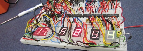
If you’re going to learn digital logic, why not aim high? That’s what [Easton] and his friend did when they built a clock using only 4000-series logic chips. On a breadboard, no less.

For a 1 Hz clock, [Easton] and his friend used a 4060 counter paired with a flip flop. This counts off 59 seconds until, with the help of an AND gate, the seconds counter rolls over to zero. After repeating that again for the minutes and building a similar circuit for the hour, and [Easton] had a working 4000-series 24-hour clock.

The breadboard clock may not be the prettiest thing, or a textbook example of how to prototype circuits,  but that was fixed with [Easton]’s friend’s PCB layout of a 12-hour clock. We couldn’t find any pics of this, but we’re sure it’s awesome and a great way to learn about logic and design.

Do You Know WHY You’re Supposed To Use Decoupling Capacitors?

[Bertho] really enjoyed pawing through the pile of projects submitted to the 7400 logic contest. But one thing kept hitting him with the vast majority of the entries: decoupling capacitors were missing from the circuits. If you’ve worked with microcontrollers or digital logic chips you probably know that you’re supposed to add a small capacitor in between the voltage and ground pins for decoupling purposes. But do you know why? [Bertho] put together a great post that looks that the benefits of using decoupling capacitors in your circuits.

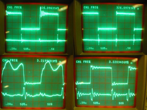
He set up a circuit using a 74HC04 inverter and put it to the test. The image above shows current measurments with the inverter under load. Images on the right show a decoupled circuit and the ones on the left shows a circuit without that capacitor. You can see that the decoupled circuit has much smoother signals when driven high. But it’s not just the smoothness that counts here. [Bertho] goes on to discuss the problem of slow rise-time caused by a dip in current flowing into a chip’s VCC pin. It can take a long time to get above the threshold where a chip would recognize a digital 1. Throwing a capacitor in there adds a little reservoir of current, just waiting to fill in when the power rail dips. This feeds the chip in times of need, keeping those logic transitions nice and snappy.

Logisim: Open Source Digital Logic Simulator

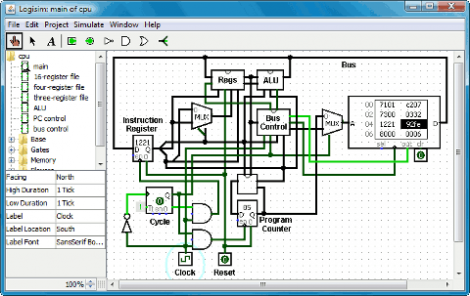
[Spi Waterwing] wrote in to make sure that we were aware of Logisim, a Java-based open source digital logic simulator. We’ve used Atanua quite a bit in the past but hadn’t heard of this program. It seems to have a pretty big educational following and right off the bat it’s got a feature we’ve always wanted, the ability to build your own ‘black box’ logic devices. That is to say you can build your own circuit out of logic gates and then package it into a part to be plopped into your next design. What it doesn’t have is the series logic chips that we’re used to with Atanua, but you can build your own with the black box feature if you really need that kind of functionality.

So grab a copy and try building that binary calculator project from last month.

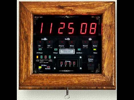
Master Clock System Uses All Logic, No Microcontrollers

What you see above is a master clock. It is the center of a system that can run an unlimited number of slave clocks, keeping them on-time thanks to its ability to synchronize with an atomic clock. [Brett Oliver] put together the project back in 2005 using digital logic chips, and no programmable microcontrollers. This includes everything from the binary decoders that drive the 7-segment displays, to the radio transceiver board that gathers the atomic clock data, to the various dividers that output 1 second, 2 second, 30 second, 1 minute, 1 hour, and 24 hour signal pulses. It’s  a well document and fascinating read if you’re interested in digital logic clocks.

8-bit Binary Calculator

binary_calculator

Don’t feel like shelling out $5 for a fancy factory made calculator that won’t even do binary math? [Jeff] decided to prove his mastery of gates and his disdain for base 10 by building a binary calculator using XOR, AND, and OR chips. Calculations can be input in two ways: through digital logic headers or by three banks of DIP switches used to enter the operator and the two operands. Although limited to addition and subtraction, this is a great way to make sure you really understand digital logic. Take a look at the rough design schematics in his album. The design is modular so if you have one of each gate and a few LEDs sitting around you can give this a whirl.

Working With VFDs

vfd

We love old display technology, like Nixie tubes, but they’re often difficult to work with because they require higher voltages than digital logic. Vacuum florescent displays (VFD) fall into this category. While not necessarily “old”, they are becoming far less common than LCDs. The main benefit of a VFD is that it actually produces light directly; it doesn’t require a backlight. You’ll find these displays on various players and appliances: CD, DVD, VCR, microwaves, stoves, car headunits, and others.

[Sprite_tm] had written off some VFDs, but recently revisited them with renewed interest. He started by testing what sort of voltage would be required to drive the display. It took 3V for the filament plus 15V to drive the grids. There are VFD controller chips available, but he wanted to get this working with what he had on hand. He had experience with older 40xx series logic, which can be powered by much higher voltages than 5V 74xx. His final schematic has three 4094 serial to parallel chips with an ATtiny2313 controller. A 5V power supply is dropped to 3V with diodes to drive the filament while a boost converter brings it up to 15V for the 4094s that switch the segments. While the code is specific to this display, it would be a great place to start your own project.