Reading Data From An Unwilling Blood Pressure Monitor

Given the modern trend of interconnecting anything and everything, we have no doubt that somebody sells a blood pressure monitor that will push its measurements out to all sorts of cloud services on your behalf. We’re equally sure that doing so requires you to sign up for some new account or service, and that there may even be a subscription cost hiding in there as well.

Looking to record his vitals on his own terms, [Tomasz Burzy] set out to modify a basic blood pressure monitor so that it would send its data out over WiFi. He succeeds in the end, but as is so often the case around these parts, the journey ended up being just as interesting as the final destination.
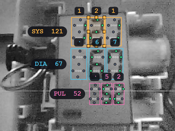
Optically detecting which LCD segments are activated.

His initial idea was to tap into the monitor’s PCB with his logic analyzer. He quickly found a test point that let him pull the raw value from the unit’s pressure sensor, and with a little massaging, he even got some code running that turned that into a fair estimation of his actual blood pressure. But it didn’t quite match what the display showed, and doing some research, he found that these monitors generally employ some unknowable Secret Sauce to derive the final result from the raw data.

Efforts to intercept the final number from the device’s main chip before it was sent off to the display driver were stymied by the fact that it was the display driver. The unit was so well integrated, presumably to drive down the cost, that there was a single IC handling essentially all aspects of its operation. So much for the logic analyzer route.

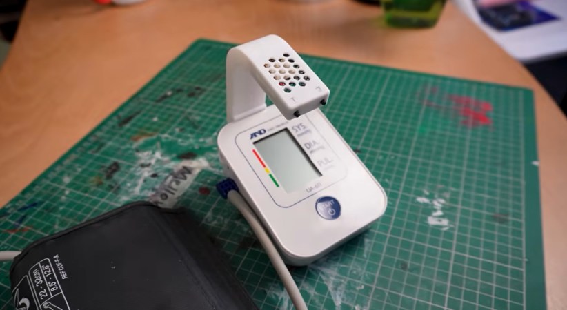
In the end, [Tomasz] took the nuclear option and used a camera mounted to the top of the unit to pull data off the display optically. But instead of a full-fat computer running some computer vision software, he’s able to pull it off on an ESP32-CAM module. How? Because he knows exactly where each segment of the LCD is, he simply needs to check a set array of coordinates in the camera’s image to see if they are lit up or not. This greatly reduces the complexity of the task, and brings it within the capabilities of the lowly microcontroller.

Although we love the idea of developing hacker-friendly medical devices that give up their data without having to jump through so many hoops, we appreciate the effort [Tomasz] put into this, and think it’s a fantastic example for similar reverse engineering efforts.

Continue reading “Reading Data From An Unwilling Blood Pressure Monitor” →
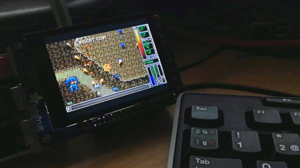
Blazing Fast Raspberry Pi Display Driver Will Melt Your Face Then Teach You How

Reader [poipoi] recently wrote into our tip line to tell us about an “amazingly fast” Raspberry Pi display driver with a README file that “is an actual joy to read”. Of course, we had to see for ourselves. The fbcp-ili9341 repo, by [juj], seems to live up to the hype! The software itself appears impressive, and the README is detailed, well-structured, educational, and dare we say entertaining?

The driver’s main goal is to produce high frame rates — up to around 60 frames per second — over an SPI bus, and it runs on various Raspberry Pi devices including the 2, 3 and Zero W. Any video output that goes to the Pi’s HDMI port will be mirrored to a TFT display over the SPI bus. It works with many of the popular displays currently out there, including those that use the ILI9341, ILI9340, and HX8357D chipsets.

The techniques that let [juj] coax such frame rates out of a not-terribly-fast serial bus are explained in detail in the README’s How it Works section, but much of it boils down to the fact that it’s only sending changed pixels for each frame, instead of the full screen. This cuts out the transmission of about 50% of the pixels in each update when you’re playing a game like Quake, claims the author. There are other interesting performance tweaks as well, so be sure to check out the repo for all the details.

There’s a video comparing the performance of fbcp-ili9341 to mainline SPI drivers after the break.

Continue reading “Blazing Fast Raspberry Pi Display Driver Will Melt Your Face Then Teach You How” →

Running Doom On The Intel Edison

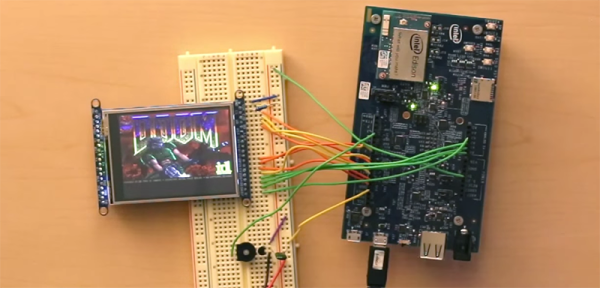
A few months ago, the Intel Edison launched with the promise of putting a complete x86 system on a board the size of an SD card. This inevitably led to comparisons of other, ARM-based single board computers and the fact that the Edison doesn’t have a video output, Ethernet, or GPIO pins on a 0.100″ grid. Ethernet and easy breakout is another matter entirely but [Lutz] did manage to give the Edison a proper display, allowing him to run Doom at about the same speed as a 486 did back in the day.

The hardware used for the build is an Edison, an Arduino breakout board, Adafruit display, speaker, and PS4 controller. By far the hardest part of this build was writing a display driver for the Edison. The starting point for this was Adafruit’s guide for the display, but the pin mapping of the Edison proved troublesome. Ideally, the display should be sent 16 bits at a time, but only eight bits are exposed on the breakout board. Not that it mattered; the Edison doesn’t have 16 pins in a single 32-bit memory register anyway. The solution of writing eight bits at a time to the display means Doom runs at about 15 frames per second. Not great, but more than enough to be playable.

For sound, [Lutz] used PWM running at 100kHz. It works, and with a tiny speaker it’s good enough. Control is through Bluetooth with a PS4 controller, and the setup worked as it should. The end result is more of a proof of concept, but it’s fairly easy to see how the Edison can be used as a complete system with video, sound, and wireless networking. It’s not great, but if you want high performance, you probably won’t be picking a board the size of an SD card.

Video demo below.

Continue reading “Running Doom On The Intel Edison” →