The Future Of Eagle CAD

Last week, Autodesk announced their purchase of CadSoft Eagle, one of the most popular software packages for electronic design automation and PCB layout.

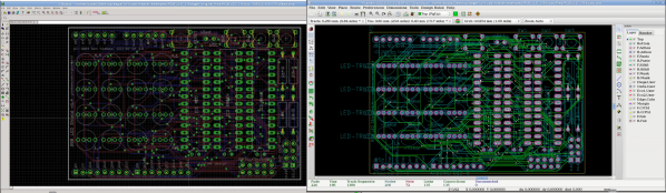
Eagle has been around for nearly thirty years, and has evolved to become the standard PCB design package for electronic hobbyists, students, and engineering firms lead by someone who learned PCB design with Eagle. The reason for this is simple: it’s good enough for most simple designs, and there is a free version of Eagle. The only comparable Open Source alternative is KiCad, which doesn’t have nearly as many dedicated followers as Eagle.  Eagle, for better or worse, is a standard, and Open Source companies from  Sparkfun to Adafruit use it religiously and have created high-quality libraries of parts and multiple tutorials

I had the chance to talk with [Matt Berggren], former Hackaday overlord who is currently serving as the Director of Autodesk Circuits. He is the person ultimately responsible for all of Autodesk’s electronic design products, from Tinkercad, 123D, Ecad.io, and project Wire, the engine behind Voxel8, Autodesk’s 3D printer that also prints electronics. [Matt] is now the master of Eagle, and ultimately will decide what will change, what stays the same, and the development path for Eagle.

Continue reading “The Future Of Eagle CAD”

The EAGLE Has Landed: At Autodesk!

The selloffs continue at Farnell! We’d previously reported that the UK distributor of electronics parts was being sold to a Swiss distributor of electronics parts. Now it looks like they’re getting rid of some of their non-core businesses, and in this case that means CadSoft EAGLE, a popular free-for-limited-use PCB layout suite.

But that’s not the interesting part: they sold EAGLE to Autodesk!

Autodesk had a great portfolio of professional 3D-modeling tools, and has free versions of a good number of their products. (Free as in beer. You don’t get to see the code or change it.) By all accounts, the professional versions of their tools are very professional if you can afford them, and the trial versions are still useful. This makes EAGLE slot very nicely into their business model, filling a hole (PCB design) in their toolchain.

What does this mean for those of you out there still using EAGLE instead of open-source alternatives? (We haven’t used EAGLE since KiCAD got good a couple years back.) Beats us! Care to speculate wildly? That’s why we have a comments section. Go! In the mean time we hope to have more info for you directly from Autodesk soon so stay tuned to the front page.

Reinventing VHDL Badly

A few years ago, Philip Peter started a little pet project. He wanted to build his own processor. This really isn’t out of the ordinary – every few months you’ll find someone with a new project to build a CPU out of relays, logic chips, or bare transistors. Philip is a software developer, though, and while the techniques and theory of building hardware haven’t changed much in decades, software development has made leaps and bounds in just the past few years. He’s on a quest to build a CPU out of discrete components.

Search the Internet for some tips and tricks for schematic capture programs like KiCad and Eagle, and you’ll find some terrible design choices. If you want more than one copy of a very specific circuit on your board, you have to copy and paste. Circuit simulation is completely separate from schematic capture and PCB design, and unit testing – making sure the circuit you designed does what it’s supposed to do – is a completely foreign concept. Schematic capture and EDA suites are decades behind the curve compared to even the most minimal software IDE. That’s where Philip comes in. By his own admission, he reinvented VHDL badly, but he does have a few ideas that are worth listening to.

Continue reading “Reinventing VHDL Badly”

Designing Flat Flexible PCBs

You can find flex PCBs in just about every single piece of consumer electronics. These traces of copper laminated in sheets of Kapton are everywhere, and designing these cables, let alone manufacturing them, is a dark art for the garage electronics wizard. Having these flat flex cables and PCBs manufactured still requires some Google-fu or a contact at a fab house, but at least now designing these cables is a solved problem.

[Oli] needed a way to connect two PCBs together over a moving part. Usually this means some sort of connector or cable, but he’s developed an even better solution – flexible PCB connections. To generate these copper traces sandwiched between a few layers of Kapton, [Oli] wrote a Python script to take a set of parameters, and produces an design for Eagle that includes all the relevant bits.

Of course, with a flexible PCB layout, the question of how to get these manufactured comes up. we’ve seen a few creative people make flexible PCBs with a 3D printer and there’s been more than one Hackaday Prize project using these flex PCBs. [Oli] says any manufacturer of flexible circuits should be able to reproduce everything generated from his script without much thinking at all. All we need now is for OSH Park to invent purple Kapton.

You can grab [Oli]’s script on his GitHub.

KiCAD BOM Management

KiCAD remains a popular tool for designing PCBs and other circuits, and with good reason: it’s versatile and it’s got pretty much everything needed to build any type of circuit board you’d want. It also comes with a pretty steep learning curve, though, and [Jeff] was especially frustrated with the bill of materials (BOM) features in KiCAD. After applying some Python and Kivy, [Jeff] now has a BOM manager that makes up for some of KiCAD’s shortcomings.

Currently, the tool handles schematic import, like-component consolidation, and a user-managed parts database that can be used to store and retrieve commonly used parts for the future. All of the changes can be saved back to the original schematic. [Jeff] hopes that his tool will save some time for anyone who makes more than one PCB a year and has to deal with the lack of BOM features native to KiCAD.

[Jeff] still has some features he’d like to add such as unit tests, a user guide, and a cleaner user interface. What other features are you anxious to see added to KiCAD?

This script is a great tool for anyone who has had similar frustrations. KiCAD is popular to modify and expand, too: there have been tools for mechanical CAD export, a parts-generator and cost-tracker, and an Eagle to KiCAD converter if you’re thinking of making the switch.

Developed On Hackaday : HaDge Update – It’s A HACK

Work on HaDge – the Hackaday con badge, continues in bits and spurts, and we’ve had some good progress in recent weeks. HaDge will be one conference badge to use at all conferences, capable of communicating between badges.

Picking up from where we left off last time, we had agreed to base it around the Atmel D21, a 32-bit ARM Cortex M0+ processor. To get some prototype boards built to help with software development, we decided to finish designing the HACK before tackling HaDge. HACK is a project that [Michele Perla] started that we have sort of assimilated to act as the prototyping platform for HaDge. We wanted a compact micro-controller board and hence opted for the SAM D21E – a 32 pin package with 26 IO’s.

[Michele Perla] had earlier designed HACK based on the larger 32 pin SAM D21G and used Eagle to hack-brddraw the schematic and layout. Using the Eagle to KiCad script, he quickly converted the project and got on to making the board layout. I took up the rear guard, and worked on making his schematic (pdf) “pretty” and building up a schematic library of symbols. While [Michele] finished off the board layout, I worked on collecting STEP models for the various footprints we would be using, most of which I could get via 3dcontentcentral.com. The few I couldn’t were built from scratch using FreeCAD. The STEP models were converted to VRML using FreeCAD. Using [Maurice]’s KiCad Stepup script, we were able to obtain a complete STEP model of the HACK board.

HACK is now ready to go for board fabrication and assembly. We plan to get about 20 boards made and hand them out to developers for working on the software. The GitHub repository has all the current files for those who’d like to take a look – it includes the KiCad source files, PDFs, gerbers, data sheets and images. The board will be breadboard compatible and also have castellated pads to allow it to be soldered directly as a module. Let us know via group messaging on the HACK project page if you’d like to get involved with either the software or hardware development of HaDge.

In a forthcoming post, we’ll put out ideas on how we plan to take forward HaDge now that HACK is complete. Stay tuned.

Eagle To KiCad Made Easy

One barrier for those wanting to switch over from Eagle to KiCad has been the lack of a way to convert existing projects from one to the other. An Eagle to KiCad ULP exists, but it only converts the schematic, albeit with errors and hence not too helpful. And for quite some time, KiCad has been able to open Eagle .brd layout files. But without a netlist to read and check for errors, that’s not too useful either.

[Lachlan] has written a comprehensive set of Eagle to KiCad ULP scripts to convert schematics, symbols and footprints. Board conversion is still done using KiCad’s built in converter, since it works quite well, and we were able to successfully convert two projects from Eagle. The entire process took only about 10 to 15 minutes of clean up after running the scripts.

The five scripts and one include file run sequentially once the first one is run. [Lachlan]’s scripts will convert Eagle multi sheet .sch to KiCad multi sheets, place global and local net labels for multi sheets, convert multi part symbols, build KiCad footprint modules and symbol libraries from Eagle libraries, create a project directory to store all the converted files, and perform basic error checking. The Eagle 6.xx PCB files can be directly imported to KiCad. The scripts also convert Via’s to Pads, which helps with KiCad’s flood fill, when Via’s have no connections — this part requires some manual intervention and post processing.